
The 555 Timer IC, invented in 1972, has become one of the most popular and widely used integrated circuits in electronics. Its versatility and ease of use make it a staple in various applications, from simple timers to complex pulse-width modulation systems. Here, we will explore the diverse applications of the 555 Timer, focusing on how it can be leveraged in electronic design and PCB projects.
Core Component in Electronic Design
The 555 timer serves as a fundamental building block in both digital and analog circuits, enabling designers to implement precise timing and control features.
The 555 timer is a cornerstone component in electronic design, widely utilized in printed circuit boards (PCBs) due to its versatility and functionality across various applications.
Its straightforward configuration allows for easy integration into electronic design projects, whether for hobbyists or professional engineers.
Key Features of 555 Timer
- Adjustable Timing: The timing intervals in astable and monostable modes can be adjusted using external resistors and capacitors.
- Wide Supply Voltage Range: It can operate over a broad voltage range (typically 4.5V to 15V), making it suitable for various applications.
- High Output Current: The output can drive loads directly, allowing it to control other devices like LEDs or small motors.
- Easy to Use: The 555 timer is simple to configure and integrate into circuits, making it popular among hobbyists and professionals alike.
How the 555 Timer Works
The 555 timer operates based on a combination of comparators, flip-flops, and discharge transistors, which together manage timing and output control. Here’s a detailed breakdown of how it works in its three main modes: astable, monostable, and bistable.
Internal Structure
The internal structure of the 555 timer consists of:
- Two Voltage Comparators: These compare the input voltage to reference voltages.
- A Flip-Flop: This stores the state of the output based on the inputs from the comparators.
- A Discharge Transistor: This discharges the timing capacitor when required.
- A resistor divider: Typically made of three resistors that set the reference voltage levels for the comparators.

Modes of Operation
1. Astable Mode
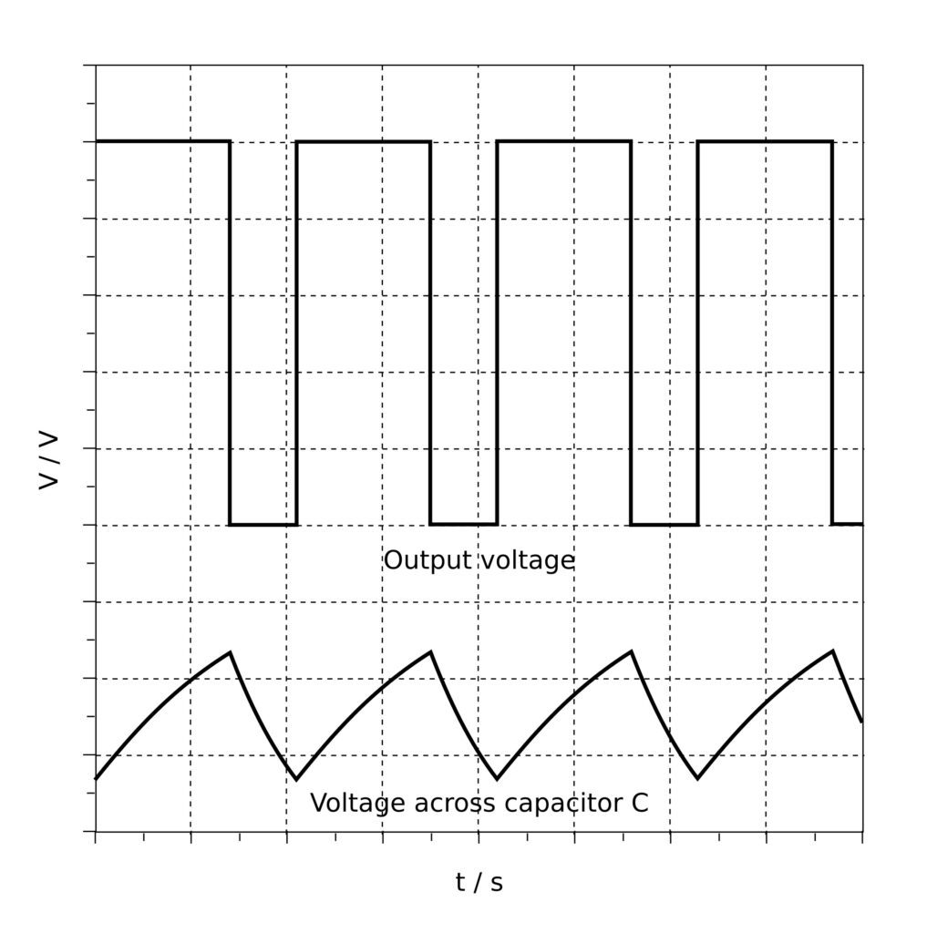
In astable mode, the 555 timer operates as an oscillator, generating a continuous square wave output.
- Configuration: Two resistors (R1 and R2) and a capacitor (C1) are connected to the timer.
- Charging and Discharging:
- The capacitor charges through R1 and R2 until it reaches 2/3 of the supply voltage (Vcc).
- Once this threshold is reached, the upper comparator triggers the flip-flop, which changes the output state to LOW and activates the discharge transistor.
- The capacitor then discharges through R2 until it reaches 1/3 of Vcc.
- When the voltage drops below this threshold, the lower comparator triggers the flip-flop again, switching the output back to HIGH and starting the cycle over.
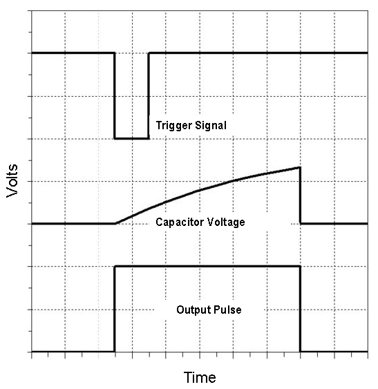
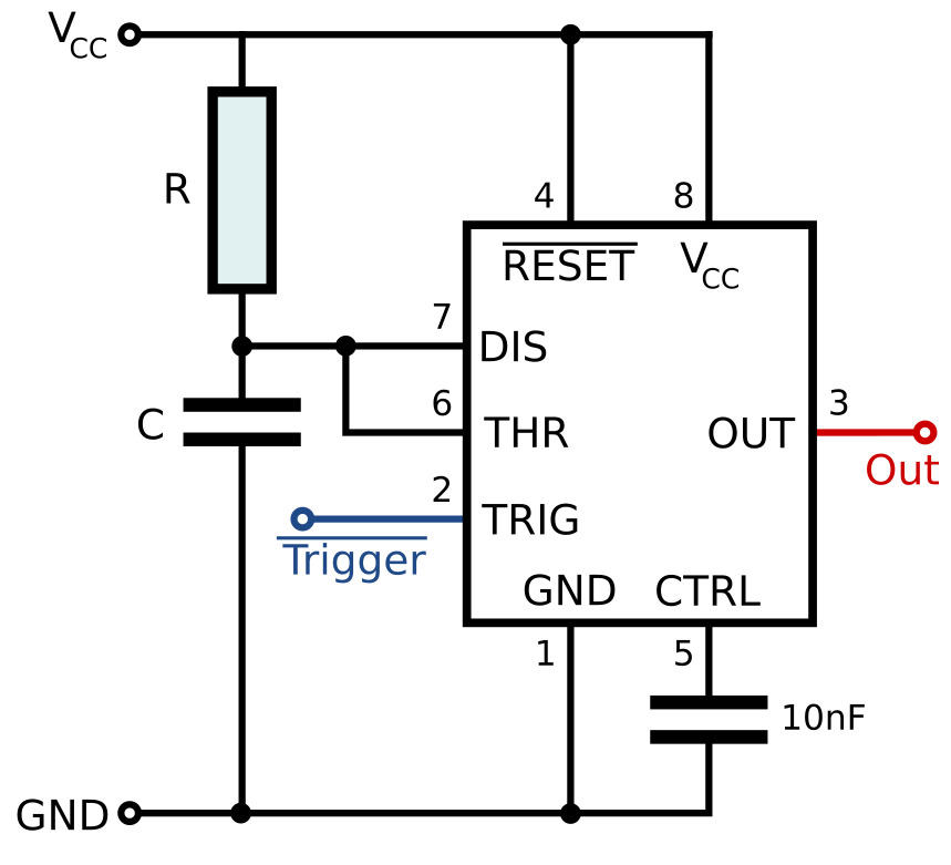
2. Monostable Mode
In monostable mode, the 555 timer acts as a one-shot pulse generator.
- Configuration: A resistor (R) and a capacitor (C) are connected to the timer, with the trigger input connected to an external signal.
- Triggering: When a negative pulse is applied to the trigger pin (TRIG), the output goes HIGH for a predetermined time period.
- Timing:
- The capacitor charges through the resistor until it reaches 2/3 Vcc.
- Once the capacitor charges to the threshold voltage, the output goes LOW, and the capacitor discharges through the discharge pin.
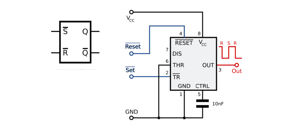
3. Bistable Mode
In bistable mode, the 555 timer functions as a flip-flop.
- Configuration: The timer is set up with two trigger inputs (TRIG and RESET).
- Operation:
- A LOW signal on the TRIG pin sets the output HIGH.
- A LOW signal on the RESET pin resets the output to LOW.
- State Change: The output state is maintained until it is triggered again, making it useful for applications like toggling outputs or storing binary states.
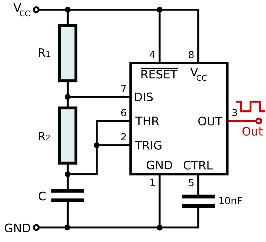
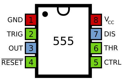
555 Timer Pin Configuration:
The standard 555 Timer IC typically has 8 pins:
GND:
Ground connection.
TRIG:
Trigger input for starting the timing interval in monostable mode.
OUT:
Output pin where the timing signal is available.
RESET:
Active-low input to reset the timer.
CTRL:
Control voltage input to adjust the timing characteristics.
THRS:
Threshold input for determining when to end the timing interval.
DISCH:
Discharge pin for discharging the timing capacitor.
VCC:
Supply voltage input.
Overall, the 555 timer is a fundamental component in electronics, valued for its reliability, versatility, and ease of use.
Applications for a 555 Timer

The 555 timer is a highly versatile integrated circuit used in a wide range of applications across various fields of electronics. Here are some common applications of the 555 Timer:
1. Timing Applications
Delay Timer:
Used in circuits to create a delay before an action occurs, such as turning on a light after a specified time.
Pulse Width Modulation (PWM):
Employed in motor speed control, dimming lights, and controlling the brightness of LEDs.
2. Oscillator Applications
Frequency Generator:
Generates square waves for audio tones, clock pulses, or signal modulation.
Tone Generator:
Used in sound-producing devices like alarms, buzzers, and musical instruments.
3. Flashing Lights
LED Flasher:
Creates blinking LED circuits for decorative lighting or indicators.
Light Chasers:
Used in circuits that light up LEDs in a sequence, such as in decorative displays.
4. Timer Circuits
One-Shot Timer:
Generates a single pulse of a specified duration in response to a trigger signal, useful in applications like timers for appliances.
Interval Timer:
Used in applications where a specific time interval between events is required.
5. Frequency Division
Clock Divider:
Divides the frequency of an input signal, commonly used in digital circuits and communication systems.
6. Pulse Generation
Square Wave Generator:
Produces square waves for testing and signal processing applications.
Random Pulse Generator:
Can be configured to produce random pulses for various applications.
7. Bistable Applications
Flip-Flop:
Acts as a bistable multivibrator, maintaining a state until triggered, useful in memory and control applications.
Switch Debouncing:
Stabilizes signals from mechanical switches to prevent multiple triggering.
8. Control Systems
Motor Control:
Used in circuits to control the speed and direction of DC motors.
Temperature Control:
In temperature control systems, it can regulate heating elements.
9. Tone and Sound Generation
Alarm Systems:
Generates sound for alarms and security systems.
Music Synthesizers:
Used in simple synthesizer circuits to produce audio tones.
10. Signal Conditioning
Signal Shaping:
Used to modify the shape of input signals for better processing in various applications.
11. Measurement Applications
Frequency Counter:
Can be used in frequency counting applications to measure the frequency of input signals.
12. Educational Tools
Learning and Experimentation:
Commonly used in educational settings for teaching basic electronics concepts.
13. Miscellaneous Applications
LED Light Patterns:
Creates various patterns for decorative lighting.
Heartbeat Simulator:
Simulates a heartbeat for medical training or testing.
Conclusion
The 555 Timer remains a fundamental component in electronics, with a wide range of applications that cater to hobbyists and professionals alike. Its ability to function in different modes allows engineers and designers to implement it in various circuits for timing, oscillation, control, and signal processing tasks. Whether you’re a beginner or an experienced engineer, exploring the applications of the 555 Timer can open up a world of possibilities in your electronic projects.