
In the field of electrical engineering, accuracy is everything. Whether in power electronics, battery monitoring systems, or low resistance measurement applications, eliminating errors in electrical measurements is crucial. One of the foundational techniques that ensure precision in such applications is the Kelvin connection, particularly when used with resistors. The Kelvin connection resistor setup helps engineers achieve ultra-precise readings by compensating for voltage drops caused by lead and contact resistance.
In this in-depth article, we’ll explore the concept of the Kelvin connection resistor, its related applications, diagrams, and variations such as its use with capacitors and current sensing, while covering key topics like low resistance measurement, shunt resistors, and the Kelvin emitter connection.
What is a Kelvin Resistor?
A Kelvin resistor, also known as a 4-terminal resistor or 4-wire resistor, is a specialized component used for precision measurement of very low resistance values. Unlike standard 2-terminal resistors, a Kelvin resistor has four separate leads: two for the current input and two for voltage measurement.
This configuration is critical because when current flows through the resistor, there is always a small voltage drop across the wires and contacts. By using two separate wires to measure the voltage directly across the resistor element, we can eliminate the effect of this parasitic resistance, thereby improving measurement accuracy.
Kelvin resistors are widely used in:
- High-precision instrumentation
- Battery management systems (BMS)
- Current sensing circuits
- Power supplies
- Calibration equipment
What is the Purpose of the Kelvin Connection?
The Kelvin connection is a method of making four-wire measurements to eliminate error from resistance in the measurement leads. The primary purpose of the Kelvin connection is to ensure accurate low-resistance measurements.
This is especially important in applications where:
- The resistance value is very low (milliohms or micro-ohms)
- Current levels are high
- Contact resistance is non-negligible
Using a 4-wire Kelvin setup, a constant current is applied through one pair of terminals, and the resulting voltage is measured across the second pair. Because the voltage sense lines carry negligible current, the resistance of these wires does not introduce a significant voltage drop, and the voltage measured reflects only the resistor’s true value.
Benefits:
- Eliminates lead resistance effects
- Increases accuracy in small resistance measurements
- Enhances performance of current sense circuits
Kelvin Connection Capacitor
While Kelvin connections are most commonly associated with resistors, they can also be applied in capacitor testing and measurement.
In high-frequency or precision impedance measurements, parasitic inductance and resistance in the capacitor’s leads can distort measurement results. A Kelvin connection capacitor setup uses four-terminal (4-wire) connections to minimize these parasitic effects, similar to resistors.
This is especially important when testing:
- Low Equivalent Series Resistance (ESR) capacitors
- High-frequency ceramic or film capacitors
- In-circuit capacitors with sensitive impedance characteristics
Kelvin-connected capacitors are common in LCR meters and other precision impedance analysis instruments.
Kelvin Connection Current Sense
One of the most valuable applications of the Kelvin connection is in current sensing. In many systems, monitoring current flow accurately is critical for safety, efficiency, and performance.
To sense current, engineers often use a low-value shunt resistor placed in series with the load. The voltage drop across this resistor is proportional to the current. However, at high currents, even the resistance of the PCB traces or wires can introduce significant voltage drops, leading to errors.
By applying a Kelvin connection across the shunt resistor:
- The voltage measurement reflects only the drop across the resistor element
- PCB trace or lead resistance is excluded from the reading
- Better accuracy is achieved, particularly in low-ohm or high-current designs
This technique is standard in:
- Battery monitors
- Motor drivers
- DC-DC converters
- Industrial automation systems
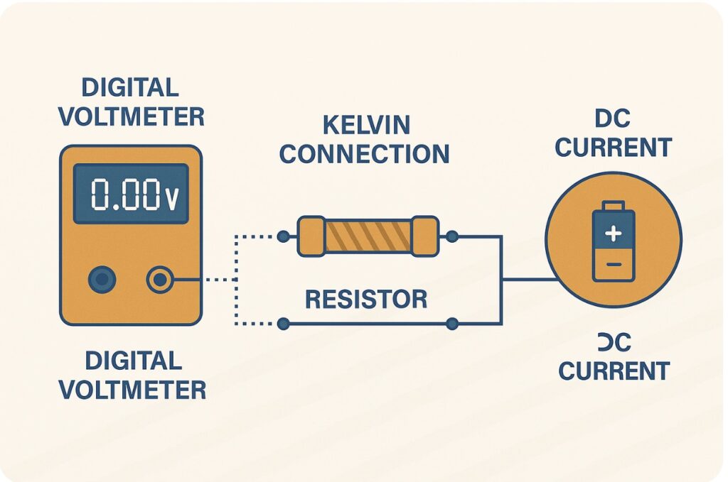
Kelvin Connection Resistor Diagram
A typical Kelvin connection resistor diagram includes:
- Two terminals for supplying current (often labeled Force+ and Force-)
- Two terminals for measuring voltage (Sense+ and Sense-)
Force+ ───┐ ┌─── Sense+
│ │
[ Resistor Element ]
│ │
Force- ───┘ └─── Sense-
This layout allows current to be driven through the resistor, while the voltage is measured across only the resistor element, independent of the connecting wires.
In practice, the sense connections are often placed as close as possible to the resistor body to minimize voltage drops due to PCB layout.
Kelvin Connection Shunt Resistor
A shunt resistor is a low-value resistor used to measure current via the voltage drop method. In high-precision systems, the shunt resistor is used in a Kelvin configuration to avoid measurement inaccuracies due to resistive elements in the PCB or wiring.
Benefits of using a Kelvin connection for shunt resistors:
- Increases the accuracy of current sensing
- Minimizes thermal drift
- Reduces noise in analog measurement circuits
Applications:
- Smart meters
- Electric vehicle battery monitoring
- Power supply load testing
- Inverter and solar charge controllers
Shunt resistors with integrated 4-terminal Kelvin pads are available commercially, and many manufacturers provide recommendations for optimal PCB layouts to maximize accuracy.
Kelvin Connection for Current Sense
To implement a Kelvin connection for current sense in a PCB design, engineers typically follow these practices:
- Use a dedicated current sense amplifier (e.g., INA219, INA240)
- Route sense lines directly to the resistor terminals
- Avoid routing sense lines in parallel with high-current paths to minimize EMI
- Place sense amplifier as close as possible to the resistor
Best practices:
- Maintain symmetrical routing to avoid mismatch
- Keep traces short and shielded where possible
- Minimize loop area to reduce noise susceptibility
The performance of current-sensing circuits using Kelvin connection techniques can approach lab-grade accuracy in compact embedded systems.
What is the Kelvin Emitter Connection?
The Kelvin emitter connection is a specific case of Kelvin sensing used in transistor circuits, especially in power electronics involving BJTs or IGBTs.
In high-speed switching applications, the emitter of the power transistor can experience significant voltage drops due to high current flowing through shared emitter resistances or parasitic inductance.
To solve this, designers use a separate emitter path:
- One emitter terminal handles the main current flow
- Another emitter terminal provides a clean voltage reference for the gate driver
This allows the gate driver to see the true emitter potential, improving switching behavior, reducing shoot-through, and minimizing gate ringing.
Common in:
- Half-bridge and full-bridge power stages
- Motor drive inverters
- High-frequency switch-mode power supplies (SMPS)
Additional Considerations in Kelvin Connections
- PCB Layout and Design
- Keep sense traces isolated from noisy digital or switching signals.
- Use guard traces or shielding when necessary.
- Temperature Effects
- Even with Kelvin sensing, temperature can affect resistance values.
- Use temperature-compensated shunt resistors where accuracy is critical.
- Measurement Equipment
- Many modern multimeters and precision instruments support 4-wire measurements by default.
- Connector Selection
- Use 4-terminal connectors where feasible for modular and removable measurement setups.
Conclusion
The Kelvin connection resistor configuration is a cornerstone technique in electrical engineering when it comes to accurate, low-resistance measurements and high-precision current sensing. Whether you’re designing a battery monitoring circuit, an industrial control system, or a power supply, using 4-wire measurement principles significantly improves system reliability and performance.
By understanding and properly implementing Kelvin connections across resistors, capacitors, shunt elements, and even transistor emitters, engineers can design more robust and accurate systems. As electronics continue to evolve toward higher speeds and lower tolerances, these techniques will remain indispensable in modern circuit design.