
USB Type-C is more than a new connector; it is a system for orientation detection, role swaps, scalable power, high-speed data, and alternate interfaces on a single port. Designing with it touches electronics, firmware, compliance, and mechanicals. If your work spans pcb design, embedded software, or product architecture, this guide lays out patterns that help you deliver ports that wake up correctly, negotiate the right power, pass tests, and keep working in the field without odd failures.
USB-C combines four major building blocks: the reversible 24-pin receptacle and cable, Configuration Channel (CC) signaling for attachment and role logic, USB Power Delivery (PD) for dynamic voltage/current contracts, and high-speed lanes for USB 3.x/USB4 plus optional alternate modes. Treat each as a subsystem with its own requirements and failure modes. The most reliable designs model attachment states up front, guard the power path, and verify layout for both RF behavior and surge/ESD survival.
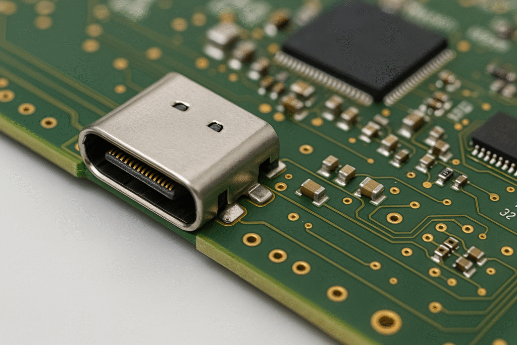
USB Type-C connector overview
A Type-C receptacle has two CC pins (CC1, CC2), a VBUS power rail, ground, two SBU pins for side-band signals, one USB 2.0 D+/D- pair, and four SuperSpeed differential pairs that are internally mapped depending on cable flip. The port detects cable orientation by sensing which CC pin connects to the plug’s CC. A source advertises current by placing Rp on CC; a sink presents Rd. Active cables and some accessories include an e-marker that is powered by VCONN supplied from the host on the unused CC pin. The SBU pins carry the AUX channel in DisplayPort Alt Mode or side-band traffic for other modes. Shell grounding and mechanical retention matter; plan for screw-lock or mid-mount styles when you expect frequent insertions.
Benefits of USB Type-C over micro-USB
Orientation is reversible, current capacity is higher, and the ecosystem supports power both ways. With micro-USB you were tied to device-as-sink and 5 V only. Type-C with PD scales from legacy 5 V down to 500 mA all the way to 48 V at 5 A with the right cable, and can swap roles so a handheld can charge an accessory or accept charge from it. SuperSpeed lanes enable multi-gigabit data and video tunneling. Accessory modes let a port present as audio adapter, debug, or vendor-defined functions. The result is fewer connectors on the product and better user experience.
USB Power Delivery (PD) basics
PD rides on the CC wire using BMC coding at ~300 kb/s and defines messages, states, and roles. Think in terms of three items: who provides power (source vs sink), who speaks USB data (DFP vs UFP), and cable capabilities (3 A vs 5 A, SPR vs EPR). A source periodically broadcasts Source_Capabilities: fixed PDOs (5 V, 9 V, 15 V, 20 V), PPS/APDO for adjustable voltage/current in small steps, and under PD 3.1, EPR levels (28 V, 36 V, 48 V). The sink evaluates these against its needs, sends a Request, the source replies Accept, performs a power transition, then signals PS_RDY. Role swaps and Fast Role Swap (FRS) allow a device to keep a partner powered during brief outages. The cable’s e-marker is read via SOP’/SOP’’ messaging to learn 5 A support and EPR status. Without an e-marked cable, plan for at most 3 A.
Alternate modes (DisplayPort, Thunderbolt)
DisplayPort Alt Mode remaps SuperSpeed pairs to carry one-, two-, or four-lane DP with the AUX channel on SBU1/SBU2. USB4 and recent Thunderbolt generations use tunneling and can fall back to DP Alt Mode; they also demand tighter loss budgets and better retimers/linear redrivers at longer trace lengths. Set expectations: if the product only needs USB 3.2 Gen 1 and PD, keep the lane budget simple; if you target USB4 or Thunderbolt, you will budget insertion loss, return loss, and eye diagrams across the whole path, including cable and any switches.
Cable identification and roles (UFP/DFP)
Get roles straight to avoid logic that oscillates or deadlocks. Power roles: Source (Rp) and Sink (Rd). Data roles: Downstream Facing Port (DFP) and Upstream Facing Port (UFP). A Dual-Role Port (DRP) toggles between Rp and Rd to discover the opposite side; the first attach sets the initial power role. Accessory identification works through specific pull configurations (e.g., Ra for passive cables). Read cable markers early: an unmarked cable supports up to 3 A; a 5 A cable must be e-marked; EPR cables are required for 28/36/48 V. If your device ever sources more than 3 A, ship a 5 A rated cable in the box and label it.
Implementing power negotiation
A minimal policy engine for a sink goes through: Wait for attach on CC → parse Source_Capabilities → pick the best PDO/APDO that meets system limits (voltage window, max current, thermal) → send Request → wait Accept/PS_RDY → enable power path → monitor current and temperature. Add retry logic and timeouts, and drop back to 5 V default if negotiation fails. For sources, publish a safe set of PDOs, gate VBUS with an ideal diode/oring controller, and police current. With PPS/APDO, clamp slew rate during voltage changes and verify converter stability across the full envelope. Keep the system up on brownouts using FRS or local hold-up capacitance. Watch the dead-battery case: most sinks must bootstrap from default 5 V first, then ask for higher voltage to start fast charging.
Current advertisement via Rp: default USB current (~500 mA/900 mA), 1.5 A, or 3 A. Many discrete designs use pull-up values near 56 kΩ (default), 22 kΩ (1.5 A), and 10 kΩ (3 A) to 5 V. Controller ICs manage this internally; check the data sheet for exact ranges. For a sink, Rd is about 5.1 kΩ. Use the controller’s ADC or comparator on CC to read partner advertisement and cable orientation.
Selecting USB Type-C controller ICs
Three categories exist. First, attach/CC logic only: parts that read CC, flip data lanes, and present pull-ups/downs. These are fine for 5 V-only gadgets. Second, PD-capable controllers that integrate the policy engine, BMC transceiver, and VCONN switch; many also drive external FETs for power path control and read current sense. Third, full power-path managers and chargers that embed buck/boost stages for sink or bidirectional use with batteries. When comparing parts, note:
• Maximum PD version and EPR support, PPS step size and range.
• Integrated gate drivers and sense amplifier accuracy.
• Role swap support (PR_Swap, DR_Swap, VCONN_Swap, FRS).
• Dead-battery operation behavior.
• Protection features: OVP, OCP, short-to-ground on SBU/CC, thermal foldback.
• I²C/SPI host interface and available firmware stack.
• Availability of reference designs and pre-certified schematics.
Choose parts with long-term supply outlook and multiple drop-in alternatives. Keep a second footprint option when possible; port controllers are often single-sourced during shortages.
PD source and sink design examples
65 W notebook adapter (source). AC-DC PFC + LLC or flyback front end produces a high-voltage rail. A synchronous buck or resonant stage generates the requested VBUS. The PD controller publishes PDOs (5/9/15/20 V) and performs PPS with a tight control loop. Current sense sits at the output with a shunt or lossless inductor method; OVP/OCP trip short the gate drivers and open the ideal diode quickly. E-marker reading verifies cable rating before allowing 5 A contracts. Thermal sensors near the connector watch temperature rise at high current; derate if contacts warm.
Portable device with 2- or 4-cell battery (sink/DRP). A buck-boost battery charger accepts a PD contract and adjusts current based on battery temperature and state of charge. The controller requests PPS to track an optimal headroom above battery voltage, improving efficiency. A system ideal diode isolates the system rail from the battery during hot-plug events. For DRP behavior, the product advertises 5 V @ 1.5 A when its battery is healthy; under brownout or depleted battery, it behaves as sink first to recover.
5 V-only accessory (UFP). A CC-logic device with Rd on CC, reverse-voltage protection FET, 20 V tolerant TVS on VBUS, and ESD on CC/SBU is enough. Add BC 1.2 DCP/CDP detection only if you must support legacy A-type hosts through adapters. Keep in mind that shorted D+/D- divider networks for BC 1.2 can add leakage that affects signal quality; gate them when the port runs at high speed.
Handling ESD and EMI for Type-C
Ports fail in two ways: signal quality problems that break SuperSpeed/USB4 and surge/ESD events that damage pins. Protect and route with a set of habits.
• Use low-capacitance TVS on SuperSpeed pairs; the parts must specify capacitance in the sub-pF to ~0.2 pF range, with clamping voltages suitable for 20 V on VBUS and ±15 kV air discharges. Place them as near to the receptacle as allowed by layout; short traces lower inductance and clamping voltage.
• Consider a common-mode choke on the SuperSpeed pairs to knock down radiated noise; pick one with minimal differential insertion loss across your data rate and watch peaking.
• Route each differential pair with tight coupling, solid return path, and no stubs. Avoid vias; if you must use them, keep pairs symmetric and use back-drilling on thick boards.
• Add TVS on CC and SBU, and protect SBU against shorts to VBUS from damaged cables.
• Stitch the connector shell to ground with several vias to create a low-impedance path for ESD.
• Keep the high-di/dt VBUS switching loop tight around the ideal diode and DC/DC.
• Verify conducted and radiated emissions with near-field probes early; small placement shifts can fix a failing port.
USB Type-C signal integrity and pcb design notes
Set targets: USB 2.0 D+/D- have a 90 Ω differential target; SuperSpeed pairs target 90 Ω differential and tight intra-pair skew (often < 5 ps per inch). Equalize trace lengths through switches and muxes. Keep connector-to-redriver total budget within allowed loss for the data rate; USB 3.2 Gen 1 is tolerant, USB4 is not. For microstrip/stripline geometry, simulate with your stack-up; include soldermask and plating in the model since it changes impedance. Ground-reference pairs continuously; if a split plane is unavoidable, bridge with a capacitor array. Reserve pads for series resistors at the controller to tame reflection if a later SI pass asks for it. Use mid-mount connectors when Z-height is tight; check that the stub from the center pads to the breakout is short. Provide test pads for CC/SBU/DP AUX and a way to clip on a passive probe near the connector without crushing the pair geometry.
Compliance testing and certification
USB-IF compliance covers electrical, protocol, power, and mechanical aspects. Plan for three buckets of testing:
• Signal integrity: USB 2.0 HS eye, jitter, and droop; SuperSpeed/USB4 return loss, insertion loss, and eye masks. Retimers/redrivers may require equalization presets per layout.
• PD protocol: attachment states, timing, state machine robustness, PPS transitions, role swaps, and behavior with out-of-spec partners. A PD analyzer/sniffer is a must; log every negotiation.
• Power and safety: OVP/OCP limits, short behavior, leakage, dielectric strength, temperature rise at 5 A, and fault clearing.
Devices and cables that pass receive a TID; many retailers and OEMs will ask for it. Keep copies of test reports and firmware loads used during testing so you can reproduce results. If you implement Alt Mode, include the relevant VESA or Intel tests. Run pre-compliance in-house on golden units before booking the official lab; small changes after layout often avoid expensive retests.
Cable quality, thermal rise, and field reliability
Real users plug cheap cables. Add protections that tolerate shorts between pins and VBUS, and verify behavior with damaged plugs. Monitor connector temperature when you allow high current; contact resistance drift can heat shells over time. Consider a thermal cutback tied to a sensor near the receptacle. Avoid running 5 A through long thin flex if the connector sits on a daughterboard. For products that live outdoors or in dusty shops, choose sealed connectors or add a dust door; debris in a port can create partial shorts that cause nuisance resets and heat. Ship the right cable in the box and document limits in the quick-start sheet.
Power architecture patterns for sinks
Three common patterns appear in handheld designs.
• Direct VBUS to charger: The PD controller requests voltage above the battery pack and hands it to a buck charger; this is simple and efficient with PPS, as the headroom can be small.
• Intermediate system rail: A buck/boost creates a regulated rail that feeds both the system and the charger; the charger sets battery current while the system pulls what it needs. This is good when the system must run without a battery.
• True path: ideal diode + charger: An ideal diode connects VBUS to the system rail so the device runs immediately on plug-in, and the charger tops up the battery. Guard startup inrush with soft-start and current sense.
For any of these, add a path to survive brief brownouts. Hold-up caps or FRS can keep the display and CPU up while a partner transitions PDOs.
Firmware checklist for policy engines
• Parse Source_Capabilities and filter PDOs by board limits (max voltage, max current, thermal).
• Prefer PPS when charging a battery; use a small headroom above pack voltage and cap slew rate.
• Implement retry and back-off on soft faults; drop to default 5 V on repeated failures.
• Log every policy event with timestamps; store a rolling window in flash for field returns.
• Support role swaps if your product powers accessories; advertise only what your power stage truly supports.
• Expose status to the app/OS: cable rating, negotiated power, temperature near the port, active mode.
• Add watchdogs for the controller and for the DC/DC; stuck states should reset cleanly.
• Test with corner cases: bad e-marker, unmarked long cable, shorted SBU, brief VBUS droop, illegal Request.
Real-world design tips and pitfalls
• Budget connectors and switches as part of the loss path; a single tiny mux can sink a USB4 layout.
• Place CC/SBU TVS so that a short to VBUS clamps safely without dumping large current into the controller.
• If you use an audio adapter accessory mode, guard against crosstalk into the microphone bias with proper filtering.
• Do not rely on a board pulldown to keep the port safe at 48 V; use a dedicated OVP and a FET that turns off fast.
• Keep a debug header that mirrors CC, SBU, and one SuperSpeed pair through a high-impedance buffer to a test card; this speeds bring-up enormously.
• Simulate the power stage’s thermal rise at the highest PDO; derate if the enclosure traps heat.
• Write a manufacturing line test that confirms lane flipping and PD exchange; a simple fixture with a PD analyzer and a known good cable catches assembly faults.
• Validate behavior with cheap third-party chargers; your product should refuse out-of-bounds PDOs and still operate on 5 V safely.
• Document your policy rules in the user manual: what power it can source, what it accepts, and what cables are required for top performance.
Mechanical and reliability details you should not skip
• Receptacle shell needs firm retention. If you use through-hole stakes plus SMT pads, verify board thickness and solder wicking so the shell bonds strongly.
• Keep a gasket or dust door for outdoor units. Moisture plus debris inside the shell causes nuisance resets or heating.
• For very thin devices, mid-mount connectors free vertical space but demand accurate pick-and-place and a flat board.
• Consider potting around the shell if the product sees vibration; avoid covering the ventilation paths that prevent condensation.
• Regularly used ports will fail mechanically before electronics; spec an insertion cycle count and pick parts from vendors that publish it. Keep a plan to refurbish units with worn shells.
Security: trust but verify the edge
USB-C opens new attack paths: malicious devices can draw unexpected current, request odd modes, or try to glitch negotiation. Add sanity checks to the policy engine: refuse out-of-range requests, clamp PPS ranges, and time-limit role swaps. Authenticate firmware for the PD controller. On systems that gate sensitive features through Alt Mode, add user confirmation in software before switching. Track cable IDs to help service teams diagnose reports tied to bad cables.
Bringing it all together
A solid USB-C design asks you to coordinate four areas: CC/PD logic, power path hardware, high-speed layout, and robust protection. Start by defining roles and limits. Pick a controller that matches them. Build a power path that tolerates shorts and surges. Route pairs with tight coupling and short stubs. Add TVS and chokes at the connector. Then run pre-compliance early, log policy events, and beat up the port with cheap cables and ESD guns. Do these steps and your product’s port will negotiate correctly, charge fast, pass tests, and keep users happy for years.
Conclusion
USB Type-C rewards careful thinking: define roles and limits first, model power contracts, route high-speed lanes by the book, and protect the connector so a bad cable does not take down the board. Treat PD as a state machine with clear logs and retries. Pick controllers and DC/DC parts you can buy for the life of the product, and keep a backup footprint in case the supply chain gets tight. With sound policy, guarded power paths, and SI-aware pcb design, a single small port can deliver charging, data, and video across your lineup without creating support headaches.