
In modern pcb design, selecting the appropriate logic family—whether Transistor-Transistor Logic (TTL) or Complementary Metal-Oxide-Semiconductor (CMOS)—is one of the most important decisions engineers make when developing digital systems. The choice affects power consumption, speed, noise immunity, interfacing, and overall performance of the circuit. Understanding the characteristics of each logic family and their variants helps designers create stable and efficient digital hardware, whether it’s for high-speed microcontrollers, low-power IoT modules, or industrial automation boards.
Overview of Logic Families
Logic families define the electrical characteristics and performance of digital circuits. Each family has unique voltage levels, power requirements, and switching behavior. Two of the most widely used families are TTL and CMOS. TTL, which originated from bipolar transistor technology, has been the backbone of digital design for decades. CMOS, built on complementary MOSFET technology, provides lower power consumption and higher noise immunity.
Modern circuits often combine both families in hybrid systems, especially in mixed-signal designs or when integrating legacy devices with new low-power architectures. Selecting the correct family ensures compatibility and predictable signal behavior across components.
TTL Characteristics and Variants (74xx, 74LS)
TTL, or Transistor-Transistor Logic, uses bipolar junction transistors (BJTs) for both logic and amplification. The standard TTL series (74xx) became an industry standard because of its predictable performance and ease of use. TTL operates typically at a 5V supply and has a logic “1” voltage above 2.0V and a logic “0” below 0.8V.
Key TTL variants include:
- 74xx Standard TTL: The original family, known for moderate speed and relatively high power consumption.
- 74LS (Low Power Schottky): This variant reduces power usage by incorporating Schottky diodes, which limit transistor saturation and improve speed.
- 74S (Schottky): Offers higher switching speed but consumes more power.
- 74ALS (Advanced Low Power Schottky): Balances speed and efficiency, often used in industrial systems.
TTL circuits are known for their robust output drive capability, allowing them to power multiple inputs. However, they consume more static power compared to CMOS circuits, even when idle.
CMOS Characteristics (HC, AC, LVC)
CMOS technology uses complementary pairs of p-type and n-type MOSFETs. When one transistor is on, the other is off, resulting in minimal static power consumption. CMOS logic families have evolved significantly over time:
- 4000 Series: The earliest CMOS family, operating at a wide voltage range (3V–15V) but slower switching speeds.
- 74HC (High-Speed CMOS): Compatible with TTL voltage levels but with higher speed and lower power.
- 74HCT (High-Speed CMOS TTL-Compatible): Designed to interface directly with TTL outputs.
- 74AC and 74ACT: Advanced CMOS families offering much faster switching speeds, suitable for high-performance digital systems.
- 74LVC (Low-Voltage CMOS): Supports modern low-voltage systems (1.8V–3.3V), used in portable and battery-powered devices.
CMOS logic provides excellent noise margins, scalability, and integration density, which is why it dominates modern IC fabrication.
Power Consumption Differences
One of the major distinctions between TTL and CMOS is their power profile. TTL devices draw continuous current even when idle because of the biasing of their BJTs. CMOS circuits, in contrast, consume nearly zero static power; current flows only during switching events when transistors charge or discharge capacitive loads.
In low-frequency or battery-operated designs, CMOS is the clear winner. However, at higher frequencies, CMOS dynamic power consumption increases due to switching activity. Engineers must balance static and dynamic power when designing high-speed systems, especially in dense pcb layouts where thermal management is critical.
Switching Speeds and Propagation Delay
Switching speed defines how fast a logic family can change states, typically measured by propagation delay (tpd). TTL circuits traditionally have faster transitions than early CMOS devices. Modern CMOS families like 74AC or 74LVC, however, surpass TTL in speed while maintaining lower power use.
Approximate propagation delays:
- Standard TTL (74xx): 10–30 ns
- 74LS: 9–12 ns
- 74HC: 8–12 ns
- 74AC: 3–5 ns
- 74LVC: 2–4 ns
Fast switching is important in microprocessor buses, memory interfaces, and high-speed signal processing. Designers must consider trace impedance, signal reflections, and crosstalk in pcb design when using ultra-fast logic families.
Output Drive Capability
Output drive determines how many inputs a gate can control—often described as fan-out. TTL outputs typically drive 10 standard TTL inputs. CMOS outputs, on the other hand, are limited by capacitive load rather than input current. This makes CMOS ideal for high-impedance signal networks but less suited to directly drive heavy loads unless buffered.
Modern logic ICs specify drive strength in milliamps (e.g., ±24 mA for 74LVC), allowing them to interface with LEDs, relays, or other digital modules without additional drivers. Designers must check fan-out limits and consider buffer stages for systems with multiple interconnections.
Noise Immunity and Voltage Thresholds
Noise immunity defines a circuit’s tolerance to unwanted voltage fluctuations. TTL circuits have fixed thresholds (about 0.8V low, 2.0V high) with limited noise margins. CMOS, on the other hand, has voltage thresholds proportional to its supply voltage (typically 30–70% of Vcc), providing better immunity.
For example, a 5V CMOS gate has a logic-high threshold around 3.5V and a logic-low around 1.5V, giving a noise margin of approximately 2V. This makes CMOS circuits more stable in electrically noisy environments, such as automotive or industrial control systems.
In high-speed pcb designs, maintaining clean signal transitions through controlled impedance and ground planes is essential for both TTL and CMOS systems to avoid false triggering or timing errors.
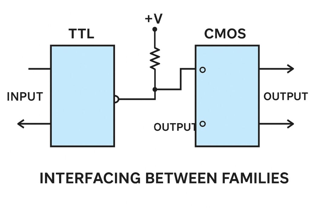
Interfacing Between Families
Interfacing TTL and CMOS can be challenging because of different voltage levels and current characteristics. TTL logic-high output (2.4V min) may not meet the CMOS input-high requirement (typically 3.5V for 5V CMOS). To resolve this, engineers use 74HCT devices—TTL-compatible CMOS—or employ pull-up resistors and level-shifting buffers.
When driving TTL inputs from CMOS outputs, it’s important to confirm the CMOS can source enough current (about 400 μA per TTL input). In mixed-voltage systems (e.g., 3.3V and 5V logic), dedicated level translators are often used to prevent damage and guarantee reliable communication.
Availability and Cost
TTL and CMOS components remain widely available from major suppliers such as Texas Instruments, Nexperia, and ON Semiconductor. TTL parts are inexpensive and favored for rugged industrial applications or legacy system maintenance. CMOS parts dominate new designs, benefiting from smaller geometries and mass production.
For large-scale integrated circuits, CMOS fabrication costs are significantly lower due to lower power dissipation, smaller die area, and compatibility with VLSI processes. TTL parts, though reliable, are gradually being phased out in many new consumer and embedded designs.
Guidelines for Selecting Logic Families
When choosing between TTL and CMOS, designers must evaluate several key criteria:
- Supply Voltage: TTL requires a fixed 5V, while CMOS supports a broader range (1.8V–15V).
- Power Efficiency: CMOS is preferred for battery-powered and portable electronics.
- Speed Requirements: TTL or advanced CMOS families (AC/LVC) serve best for high-speed designs.
- Noise Environment: CMOS offers higher noise margins, ideal for industrial and automotive settings.
- Compatibility: When working with legacy systems, TTL or HCT devices are better choices.
- Fan-out Needs: TTL excels in driving multiple inputs; CMOS requires buffering for heavy loads.
- Temperature Range: TTL handles wider industrial temperatures, though modern CMOS now meets or exceeds this range.
- Interfacing Needs: Mixed-signal systems may require level shifters or hybrid logic to interface correctly.
Good pcb design practices—such as short trace lengths, solid ground planes, and proper decoupling capacitors—help any logic family perform at its best.
Future of Logic Technologies
The evolution of logic families continues as semiconductor processes shrink and new architectures emerge. Low-voltage CMOS (LVC, AUC, AUP) has largely replaced older 5V logic in favor of 3.3V and 1.8V systems. These families combine high speed with minimal power, making them ideal for mobile, IoT, and AI-edge hardware.
Programmable logic devices (PLDs) and FPGAs now incorporate both TTL and CMOS input thresholds, giving designers flexibility to interface with a wide range of devices. With advancements in FinFET and GaN transistor technologies, future logic families will likely operate at even lower voltages while maintaining superior switching performance.
In modern digital design, understanding the nuances of TTL and CMOS remains vital. Even though CMOS dominates, legacy TTL circuits still exist in aerospace, defense, and industrial control systems where reliability and proven behavior outweigh miniaturization.
Conclusion
Selecting the appropriate logic family impacts every aspect of circuit reliability, speed, and efficiency. TTL remains relevant for rugged, high-drive applications, while CMOS provides unmatched energy efficiency and flexibility across voltage ranges. In modern pcb design, combining the strengths of both through careful interfacing and proper signal conditioning ensures that every digital system performs predictably and efficiently.