
In the modern world of pcb design and electronic product development, safety and reliability are not optional—they are fundamental. As electronics find their way into critical systems such as medical devices, automotive control units, industrial automation, and aerospace applications, the potential consequences of a design failure grow increasingly severe. A single overlooked fault in circuitry or firmware can lead to system malfunctions, user injury, or catastrophic damage. This is where hazard analysis and risk assessment play a central role in the electronics industry.
The goal of hazard analysis is to identify potential sources of harm, evaluate their likelihood, and develop strategies to minimize or eliminate associated risks. Risk assessment, on the other hand, quantifies or qualifies the severity and probability of those hazards. Together, they form the backbone of every reliable electronic system—from medical monitoring equipment to autonomous vehicles.
Importance of Risk Assessment
Risk assessment is an organized approach to identifying potential failures before they occur. In electronics, it guides engineers in developing safe designs, selecting components, and establishing preventive controls. Early identification of hazards allows for design modifications that can prevent costly recalls or accidents.
For industries such as automotive or healthcare, where safety regulations are strict, performing risk assessments is not only good practice—it is a mandatory step for regulatory compliance. For instance, ISO 26262 governs functional safety in automotive electronics, while ISO 14971 defines risk management for medical devices. By embedding risk management into each stage of the product lifecycle, from concept to decommissioning, companies protect both their users and their brand reputation.
Beyond compliance, risk assessment helps reduce production costs and field failures. When hazards are identified early, circuit redesign or part replacement can occur before full-scale manufacturing begins, saving time and resources.
Identifying Hazards in Electronics Design
Hazard identification begins with understanding how an electronic product interacts with its environment and user. Hazards can stem from electrical, mechanical, thermal, chemical, or software sources. Common hazards in electronics include:
- Electrical hazards: Overvoltage, short circuits, electrostatic discharge (ESD), and current leakage.
- Thermal hazards: Overheating due to poor thermal management or component overload.
- Mechanical hazards: Physical failure from vibration, shock, or poor mounting.
- Software hazards: Faulty algorithms or control logic leading to unsafe operation.
- EMI/EMC hazards: Electromagnetic interference disrupting nearby circuits.
During the pcb design stage, engineers analyze possible points of failure such as trace width inadequacy, grounding issues, component derating, and isolation spacing. Techniques such as worst-case analysis, stress testing, and design simulations are employed to predict abnormal behaviors before physical prototypes are produced.
Risk Matrices and Severity Levels
Once hazards are identified, they must be prioritized. The most widely used method for risk prioritization is the risk matrix, which plots the severity of harm against its probability of occurrence.
Severity levels can be categorized as:
- Negligible: No injury or minimal operational impact.
- Minor: Reversible injury or small performance degradation.
- Major: Significant damage or possible injury.
- Critical: Serious injury or life-threatening risk.
- Catastrophic: Multiple fatalities or system loss.
Probability levels may range from “frequent” to “rare.” Combining these two dimensions provides a visual map for determining which risks need immediate mitigation. For example, a hazard with high severity but low probability still requires attention if its outcome could be life-threatening.
Quantitative vs Qualitative Analysis
Risk analysis can be performed either quantitatively or qualitatively, depending on the nature of the system and available data.
- Qualitative analysis relies on expert judgment, categorizing risks as high, medium, or low. This approach is suitable during early design stages when data is limited.
- Quantitative analysis assigns numerical values to risk parameters, using statistical data or failure rates (e.g., Mean Time Between Failures, MTBF). This method is common in highly regulated sectors, providing measurable insights into risk exposure.
In advanced electronics, a hybrid approach is often preferred—qualitative assessment for initial hazard screening, followed by quantitative modeling for critical components.
Compliance with ISO 14971 and ISO 26262
Compliance standards form the foundation for risk assessment in safety-critical electronics. Two of the most important ones are ISO 14971 for medical devices and ISO 26262 for automotive electronics.
ISO 14971 focuses on identifying risks associated with medical devices throughout their lifecycle. It mandates manufacturers to establish a documented process for hazard analysis, risk evaluation, control measures, and post-market surveillance. For medical PCBs, this involves considering patient contact, isolation distances, sterilization tolerance, and fault protection.
ISO 26262 governs functional safety for road vehicles. It introduces Automotive Safety Integrity Levels (ASIL A–D), which define the required rigor of safety activities based on potential harm. Systems such as braking, steering, and airbag control must undergo deep risk analysis to avoid single-point failures.
Both standards emphasize traceability and documentation, requiring a clear link between identified hazards, mitigation actions, and verification tests.
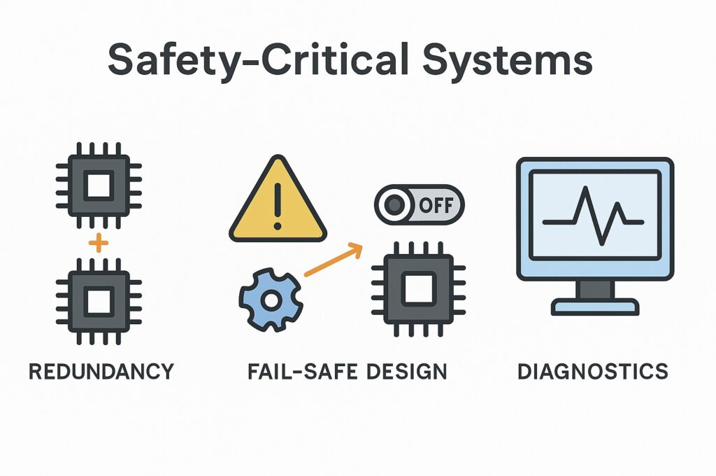
Safety-Critical Systems
Safety-critical systems are electronic assemblies where failure can lead to catastrophic outcomes. Examples include pacemakers, flight control computers, nuclear plant monitors, and autonomous driving modules. These systems require redundant designs, fault tolerance, and continuous monitoring.
Key principles in safety-critical electronics include:
- Redundancy: Using multiple components or systems to perform the same function in case one fails.
- Fail-safe design: Ensuring the system defaults to a safe state upon failure.
- Diversity: Implementing different technologies or architectures for redundancy to prevent common-cause failures.
- Diagnostics: Real-time fault detection and reporting to maintain system integrity.
Fault Tree Analysis (FTA)
Fault Tree Analysis is a top-down approach that starts from an undesired event (e.g., system failure) and traces back to its possible root causes. Engineers build a logic diagram showing relationships between component failures, software errors, or environmental conditions.
FTA helps visualize how combinations of faults can lead to a hazardous event. It uses Boolean logic gates such as AND/OR to link contributing factors. The method is especially useful in high-dependability systems, where understanding all failure paths is essential for designing effective safeguards.
For instance, in a medical infusion pump, an FTA may identify that a sensor failure combined with software delay can lead to an overdose risk. By modifying hardware thresholds or implementing secondary monitoring, such a hazard can be prevented.
Failure Mode and Effects Analysis (FMEA)
While FTA looks from top-down, FMEA is a bottom-up technique. It systematically evaluates each component or process step to determine how it might fail and what the impact would be. FMEA calculates a Risk Priority Number (RPN) based on:
- Severity (S): Consequence of the failure.
- Occurrence (O): Likelihood of the failure happening.
- Detection (D): Probability that the failure will be detected before causing harm.
RPN = S × O × D
Failures with high RPN values are prioritized for corrective actions. For example, in pcb design, if a voltage regulator failure can lead to system shutdown and there is no redundancy, the RPN will be high, triggering a redesign or component upgrade.
Mitigation Strategies
Mitigation strategies aim to eliminate hazards or reduce their risks to acceptable levels. Effective methods include:
- Component derating: Operating components below their maximum ratings to increase reliability.
- Protective circuits: Adding fuses, current limiters, or surge suppressors to handle overloads.
- Thermal management: Using heat sinks, copper pours, and controlled airflow to prevent overheating.
- Grounding and shielding: Preventing EMI/EMC interference in sensitive analog or digital circuits.
- Software safeguards: Implementing watchdog timers, safe states, and diagnostic routines.
- Isolation barriers: Physically and electrically separating high-voltage sections from low-voltage logic.
All these strategies must be validated through testing—thermal cycling, fault injection, and environmental stress screening are commonly used to confirm safety margins.
Documentation and Traceability
Proper documentation is not just a bureaucratic requirement—it is the backbone of accountability in hazard analysis and risk assessment. Every hazard identified, every mitigation implemented, and every test conducted should be traceable to a requirement.
Key documents include:
- Hazard and Risk Analysis (HRA) reports
- FMEA and FTA records
- Design verification and validation results
- Corrective action reports
- Test protocols and trace matrices
Traceability allows regulators and auditors to verify that all identified risks have been addressed. It also helps in post-market analysis if field issues arise, providing a direct link back to design decisions.
Continuous Monitoring and Review
Risk assessment does not end once a product is released. Continuous monitoring throughout the product’s life is essential. Post-market surveillance captures real-world performance data, helping detect unexpected faults or new hazards.
Periodic reviews should reassess risks considering new technologies, software updates, and field data. For connected devices, cybersecurity vulnerabilities now form part of hazard analysis since they can directly affect safety.
Implementing a closed-loop system—where feedback from testing, production, and user experience continuously refines risk controls—ensures long-term reliability and compliance.
Conclusion
Hazard analysis and risk assessment are central pillars of modern electronic design. From pcb design to system integration, they provide the structure needed to build reliable, safe, and compliant products. Applying methods such as FMEA, FTA, and risk matrices allows engineers to anticipate potential failures before they happen. Compliance with international standards like ISO 14971 and ISO 26262 reinforces this discipline, ensuring that safety is an inherent characteristic of every product, not an afterthought.
By incorporating risk management from concept to end-of-life, electronic systems can achieve higher safety integrity, fewer recalls, and stronger user trust.