
Integrated Circuit (IC) board design plays a critical role in modern electronic design, as it allows complex circuits to be embedded in compact, efficient forms. The design of IC boards is integral to the development of virtually all electronic devices, from smartphones to industrial control systems. ICs are often mounted on printed circuit boards (PCBs) to form the functional core of these devices. This article will explore how ICs are designed, their role on a board, and the processes involved in bringing an IC from concept to production.
How is an IC Designed?
The design of an integrated circuit (IC) involves several stages, each requiring precision, advanced tools, and thorough testing. The process begins with defining the requirements of the IC, such as functionality, power consumption, speed, and cost considerations. After the requirements are set, engineers develop the architecture of the IC, outlining its core functionalities and how they will interact. This high-level design phase is followed by the creation of the micro-architecture, which provides more detailed specifications of each component within the IC.
Once the micro-architecture is defined, the IC design moves to the implementation stage, where the actual logic gates and circuit paths are designed using specialized software. After implementation, the design goes through rigorous testing and bringup stages, where prototypes are tested to ensure they meet all specifications. Finally, the IC enters productization and sustaining stages, where it is optimized for mass production and supported through its lifecycle.
What is an IC on a Board?
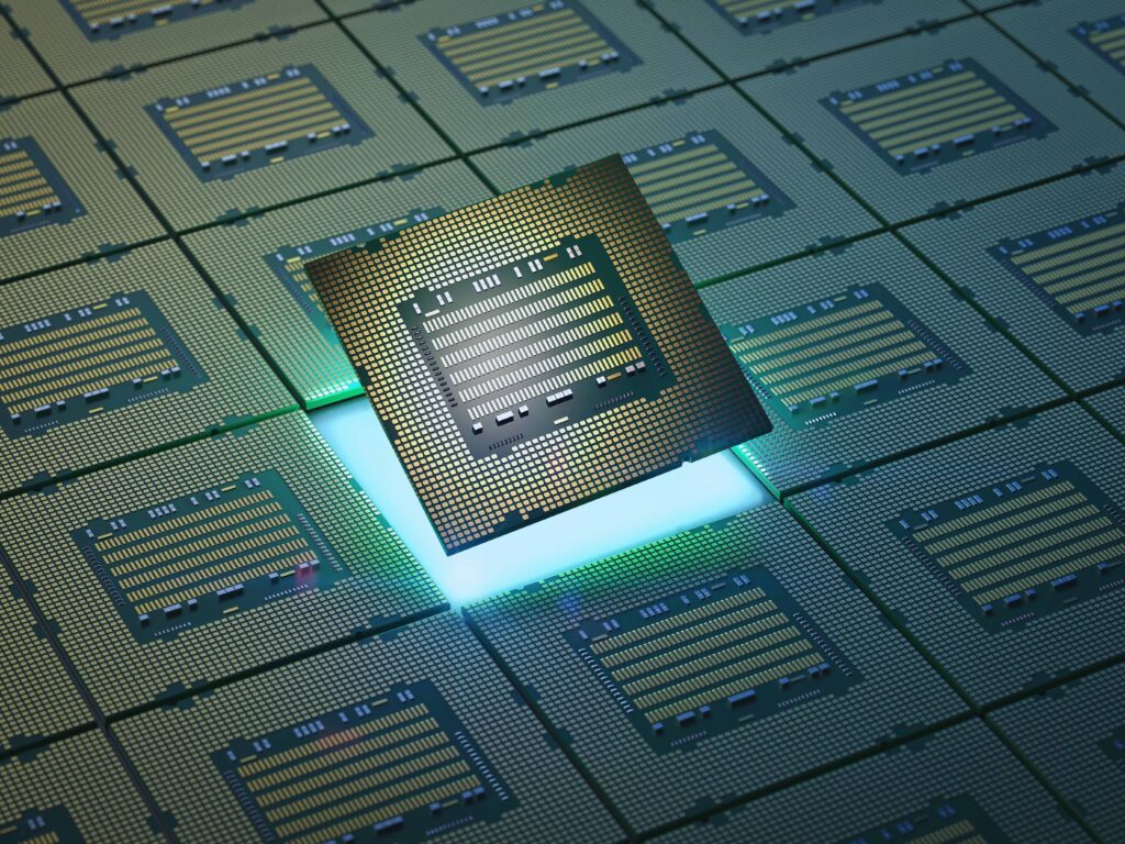
An IC on a board refers to an integrated circuit mounted on a printed circuit board (PCB). The IC serves as the central processing unit or specialized component that executes key functions within an electronic system. ICs can range in complexity from simple logic gates to highly complex microprocessors or memory modules. These ICs are soldered onto the PCB, connecting them with other components such as resistors, capacitors, and transistors, creating a fully functional electronic device.
What Does IC Stand for in Design?
In design, IC stands for Integrated Circuit. An IC is a semiconductor chip that contains millions or even billions of transistors, capacitors, and resistors etched into a tiny piece of silicon. ICs are used in a vast array of applications, including computing, telecommunications, automotive systems, and consumer electronics. The design of an IC requires specialized knowledge in electronics, semiconductor physics, and computer-aided design (CAD) tools.
What is the Difference Between IC Board and PCB Board?

While both IC and PCB are essential components in electronic devices, they serve different purposes and are constructed differently.
IC (Integrated Circuit):
An IC is a single chip that houses a miniaturized circuit made from semiconductor materials like silicon. It may contain millions of transistors and performs specific functions, such as amplification, data processing, or memory storage.
PCB (Printed Circuit Board):
A PCB is a flat board that provides a platform for mounting ICs and other components. It consists of layers of copper traces that connect the components together, enabling the IC and other parts to communicate and function as a system.
Essentially, the IC is a single component mounted on the PCB, while the PCB provides the framework for multiple components to interact and function together.
How Do You Identify IC on PCB?
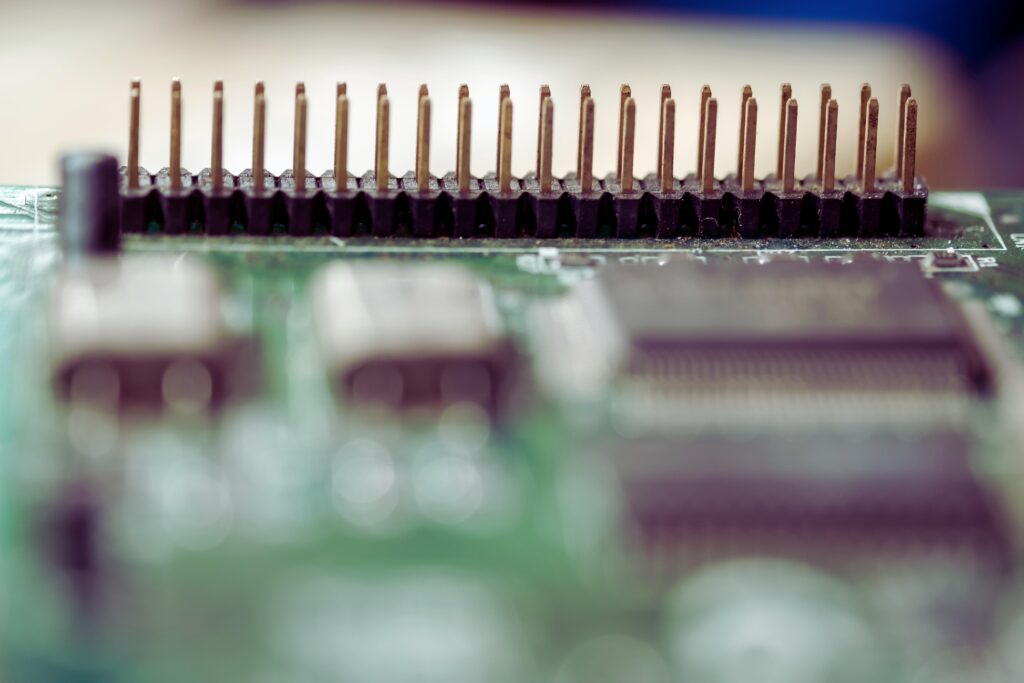
To identify an IC on a PCB, look for a small, black, square or rectangular chip with multiple pins (legs) extending from its sides. These pins connect the IC to the rest of the circuit via copper traces on the PCB. Each IC usually has a unique identifier or part number printed on it, which can be cross-referenced with a datasheet to determine its function. ICs can vary in size and shape, depending on their function and complexity, but their multiple pins and compact form make them easy to identify among other components on the PCB.
Design Lifecycle
The lifecycle of an IC design can be broken down into several distinct stages:
Requirements
The requirements phase involves defining what the IC needs to do. This includes outlining its functionalities, performance metrics, power consumption, and cost targets. These requirements form the foundation upon which the entire IC design process is built.
Architecture
Once the requirements are defined, the next step is developing the architecture of the IC. This involves determining the overall structure of the IC, including how different functions will be implemented and how they will interact with each other. The architecture also defines the system-level features and the high-level design goals.
Micro-architecture
The micro-architecture phase breaks down the high-level architecture into specific components and subsystems. This stage defines how the individual elements of the IC will be designed, such as memory blocks, arithmetic units, and input/output controllers. It provides more detailed specifications for each part of the IC.
Implementation
During the implementation phase, engineers use specialized design tools to convert the micro-architecture into actual logic gates and circuits. This involves coding the design in hardware description languages (HDLs) like Verilog or VHDL and running simulations to ensure the design meets its specifications.
Bringup
The bringup phase involves testing the first prototypes of the IC. Engineers will load test programs onto the IC and run diagnostics to ensure that it functions as expected. This stage is critical for identifying any design flaws or manufacturing defects.
Productization
Once the IC passes the bringup phase, it moves into productization, where it is optimized for mass production. Engineers work to ensure that the IC can be manufactured efficiently and at scale without compromising on quality.
Sustaining
The final stage is sustaining, which involves supporting the IC throughout its lifecycle. This includes making any necessary updates or fixes and providing ongoing support to customers.
Design Process
The IC design process is highly complex and involves several steps:
Microarchitecture and System-Level Design
At the start of the design process, the microarchitecture and system-level design define the IC’s structure and functionality. This step outlines how different modules within the IC will interact and how data will flow between them.
RTL Design
The RTL (Register Transfer Level) design stage is where engineers begin coding the IC’s functionality in a hardware description language. RTL design defines the behavior of the IC at a high level, specifying how data is transferred between registers, how arithmetic operations are performed, and how control signals are managed.
Physical Design
Once the RTL design is complete, the next step is physical design, where the abstract logic of the IC is translated into actual physical components. This involves placing the logic gates and circuits on a silicon wafer and routing the connections between them. The physical design process is critical for ensuring that the IC operates efficiently and meets all performance specifications.
Conclusion
The design of IC boards is a complex and multi-stage process that requires a deep understanding of electronics, semiconductor physics, and design tools. ICs form the backbone of modern electronic systems, and their integration onto PCBs allows for the creation of highly efficient and compact devices. From defining the requirements and architecture to implementation and physical design, every step in the IC design process is crucial for creating a successful product. Whether it’s identifying an IC on a PCB or understanding the intricate details of its design lifecycle, a clear understanding of these concepts is essential for anyone working in electronics or technology development.