
Understanding how a BLDC motor controller works is essential for engineers developing applications in robotics, drones, electric vehicles, and industrial automation. A BLDC (Brushless DC) motor cannot run on direct DC voltage alone—it needs an electronic controller to sequence power into its stator windings. From commutation logic to position detection and power electronics, every component in the controller plays a role in driving the motor efficiently. Modern controllers combine advanced pcb design, switching devices, sensors, and digital algorithms to achieve smooth, efficient, and reliable operation. This guide provides a detailed technical overview of BLDC controllers, explaining their structure, working principles, and real-world applications.
The Evolution from Brushed to Brushless Motors
Traditional brushed DC motors relied on mechanical brushes and commutators to switch current in windings. While simple, they suffered from wear, sparking, and limited efficiency. BLDC motors replaced mechanical commutation with electronic control, offering:
- Higher efficiency due to reduced friction and energy loss.
- Longer lifespan, since no brushes wear out.
- Precise torque and speed control through electronics.
- Compatibility with automation systems and IoT applications.
This shift required not only improved motor designs but also dedicated electronic controllers capable of generating commutation sequences digitally.
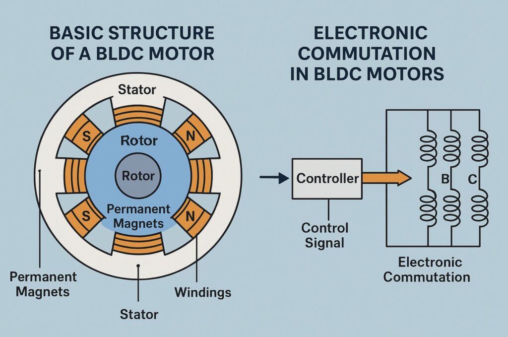
Basic Structure of a BLDC Motor (Rotor, Stator, and Windings)
A BLDC motor consists of two main parts:
- Rotor: Permanent magnets mounted on the shaft.
- Stator: Electromagnetic coils arranged in three phases (A, B, C).
- Windings: Energized in sequence to create a rotating magnetic field.
The controller applies voltages to these windings in a timed sequence, aligning stator fields with rotor magnets to produce continuous rotation. Unlike brushed motors, timing is not mechanical but electronic, requiring accurate position information.
Why Electronic Commutation Is Needed in BLDC Motors
Electronic commutation replaces the mechanical switch with semiconductor devices such as MOSFETs or IGBTs. The controller must determine:
- Which phase windings should be energized.
- In what order they should be switched.
- How much current should be applied based on load demand.
The commutation process is typically done in six steps for trapezoidal control or continuously with sinusoidal/field-oriented control (FOC). This not only ensures torque production but also optimizes efficiency and reduces vibration.
Sensor-Based Control: How Hall Sensors Detect Rotor Position
In sensor-based controllers, Hall effect sensors are embedded inside the motor near the rotor magnets. As the rotor turns:
- Each sensor detects north or south poles.
- The sensor outputs digital pulses that indicate position.
- The controller reads these signals and switches phases accordingly.
Advantages include simple implementation and reliable startup. However, sensors add cost, wiring complexity, and potential failure points in harsh environments.
Using Encoders and Optical Devices for High-Precision Control
For applications requiring precision, such as robotics and CNC machines, optical encoders or magnetic resolvers replace Hall sensors.
- Optical encoders use light beams and coded disks to measure shaft position with high resolution.
- Resolvers provide absolute angular position even in noisy environments.
These methods allow for smoother torque, precise positioning, and advanced closed-loop control, making them popular in industrial automation.
Sensorless Control Explained: Measuring Back-EMF Signals
Sensorless control eliminates physical sensors by measuring the back electromotive force (back-EMF) generated in stator windings as the rotor moves. Since one phase is unpowered at any time during trapezoidal commutation, the back-EMF in that phase is used to estimate rotor position. Benefits include:
- Lower cost and simpler hardware.
- Higher reliability due to fewer components.
- Compact design with fewer wires.
However, sensorless control requires sophisticated algorithms and works best once the motor is already spinning.
Startup Challenges in Sensorless Controllers
A drawback of sensorless controllers is startup. At zero speed, no back-EMF is generated, making rotor position undetectable. Solutions include:
- Using open-loop startup sequences (predefined commutation steps).
- Applying short pulses to align the rotor before switching to closed-loop mode.
- Hybrid controllers that use Hall sensors for startup and switch to sensorless operation at speed.
Startup optimization is a key challenge for drones and EVs, where immediate torque response is necessary.
Accuracy vs. Cost: Trade-Offs Between Sensor and Sensorless Methods
Choosing between sensor-based and sensorless control depends on application priorities:
- Low-cost consumer products (fans, pumps, drones): sensorless is preferred.
- High-performance robotics and EVs: sensors or encoders are often required.
- Industrial automation: redundancy may include both methods for reliability.
Engineers must balance accuracy, cost, space constraints, and failure tolerance when selecting the right approach.
DSP Algorithms and Modern Approaches to Sensorless Control
Modern controllers increasingly rely on Digital Signal Processors (DSPs) and microcontrollers to implement sophisticated algorithms:
- Field-Oriented Control (FOC): Calculates rotor flux and torque directly, providing smooth sinusoidal commutation.
- Extended Kalman Filters (EKF): Estimate rotor position and speed in noisy environments.
- Sliding Mode Observers: Improve robustness against parameter variations.
These software-driven approaches allow controllers to adapt dynamically to motor loads, optimize efficiency, and provide real-time feedback.
Real-World Applications of Each Method (Robotics, Drones, EVs)
- Robotics: Encoders and resolvers ensure precise movement in industrial arms and autonomous robots.
- Drones: Lightweight, cost-effective sensorless controllers are used for high-speed motors.
- Electric Vehicles: IGBT-based controllers with Hall sensors or encoders enable smooth acceleration and regenerative braking.
- Medical Devices: High-precision optical encoders ensure accuracy in pumps and surgical robots.
Each industry prioritizes different factors such as weight, cost, or accuracy, influencing controller design and architecture.
The Role of PCB Design in BLDC Controllers
A BLDC controller’s performance depends heavily on pcb design. Key aspects include:
- Thermal management: Heat sinks, copper pours, and thermal vias prevent overheating.
- Signal integrity: Proper grounding and shielding minimize noise.
- Current capacity: Wide traces and reinforced vias handle motor currents.
- Compact design: Multi-layer PCBs integrate power and control circuits efficiently.
Well-optimized PCB layouts improve efficiency, extend component lifespan, and reduce electromagnetic interference.
Power Electronics in BLDC Controllers
The switching stage typically uses:
- MOSFETs for low-voltage, high-speed control (drones, appliances).
- IGBTs for high-voltage, high-current applications (EVs, industrial drives).
- Gate drivers to ensure fast switching with minimal losses.
Correct component selection and layout are essential for reliability.
Communication Interfaces in Modern Controllers
Industrial and automotive BLDC controllers often integrate communication protocols:
- CAN bus for EVs and industrial machinery.
- RS-485 or Modbus for automation networks.
- I2C/SPI for embedded systems and consumer devices.
This allows for monitoring, diagnostics, and integration into larger systems.
Thermal Management in BLDC Controllers
Thermal issues are critical in compact controllers. Solutions include:
- Copper planes for heat spreading.
- Aluminum substrates in power PCBs.
- Liquid cooling for EV controllers.
- Smart power throttling based on temperature feedback.
Efficient heat handling ensures consistent performance and prevents damage.
Conclusion
Understanding how a BLDC motor controller works requires looking at both the motor’s structure and the controller’s electronic design. Whether using Hall sensors, encoders, or sensorless algorithms, the goal remains the same: align the stator’s magnetic field with the rotor for efficient torque production. Controllers integrate power electronics, DSP algorithms, and optimized pcb design to achieve this reliably across applications from drones to EVs. As technology advances, future controllers will rely even more on intelligent algorithms, compact designs, and energy efficiency to meet the growing demand for precise motion control.