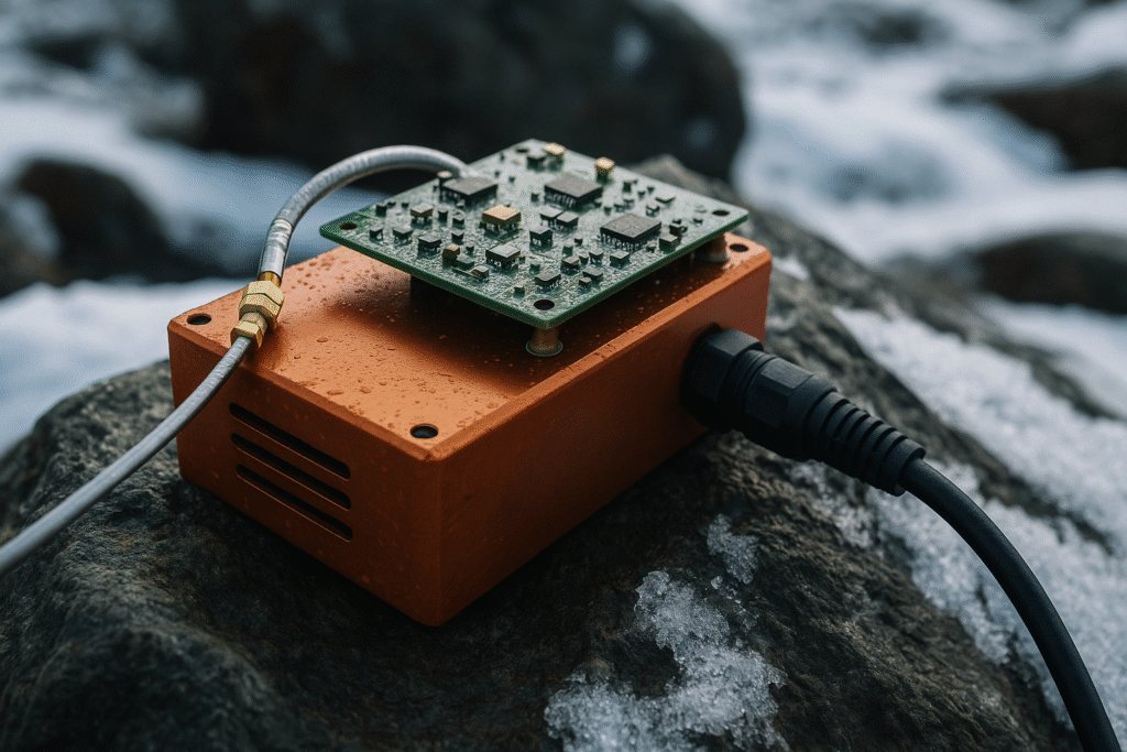
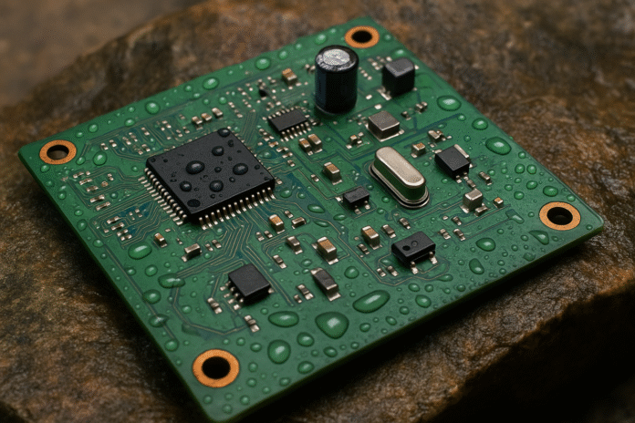
Designing electronics that perform reliably in extreme environments is one of the most challenging areas of engineering. Whether deployed in the scorching heat of a desert, the freezing cold of the Arctic, deep underwater, or exposed to radiation in space, such systems must endure stresses that conventional consumer electronics never face. Every component, from microcontrollers to passive elements and connectors, must be selected, tested, and integrated with durability in mind.
A successful extreme-environment electronic system begins with reliable pcb design. The board layout, substrate material, and interconnect strategies influence how well the device resists thermal cycling, moisture ingress, vibration, and chemical exposure. This article covers the key considerations, materials, strategies, and validation techniques engineers should follow to create electronics capable of surviving and performing in harsh conditions.
Environmental Categories for Harsh Electronics
Before designing, it’s important to understand the types of extremes electronics might face:
- High temperature (above 85°C): Downhole drilling tools, engine control units
- Low temperature (below –40°C): Polar sensors, space probes
- High humidity: Tropical and underwater devices
- Radiation exposure: Spacecraft, nuclear systems
- Mechanical shock and vibration: Automotive, aerospace, military
- Corrosive chemicals or salt fog: Marine equipment, industrial control systems
- High altitude or vacuum: Avionics and satellite payloads
Each category presents its own risks to reliability and performance. The goal is to account for worst-case scenarios in all design aspects.
Material Selection for Harsh Environments
The performance of electronic systems starts with materials. Special considerations must be made when choosing substrates, solder, component packaging, and enclosure materials.
1. PCB Substrate Materials
Standard FR4 is cost-effective but limited in thermal and moisture resistance. Alternatives include:
- Polyimide: Handles up to 260°C, low thermal expansion
- PTFE (Teflon): Excellent for high-frequency RF applications and low dielectric loss
- Rogers laminates: Suitable for RF circuits in varying climates
- Ceramic (Alumina, AlN): High thermal conductivity, used in aerospace and military
2. Solder and Metallurgy
High-temp environments require:
- Pb-rich solder alloys: Have higher melting points than Sn-based alternatives
- Gold and silver finishes: Resist corrosion and tarnishing
- Nickel plating: Acts as a barrier to diffusion and oxidation
3. Component Packaging
Plastic packaging may degrade at high temperatures or absorb moisture. Prefer:
- Ceramic-packaged ICs: Superior thermal stability and hermetic sealing
- Metal-can transistors: Used in aerospace for durability
- Conformal coatings: Provide moisture and contamination protection
4. Cable and Connector Materials
Harsh environments require high-flex, UV-resistant cables. Look for:
- PTFE or Teflon jackets
- Stainless steel connectors
- IP68-rated or hermetically sealed interconnects
PCB Design Considerations for Harsh Conditions
1. Thermal Management
High temperatures accelerate aging of semiconductors and passive elements. Use:
- Thick copper planes: Improve heat dissipation
- Thermal vias: Transfer heat to opposite board layers
- Copper pours under hot components: Spread thermal energy
- Thermal simulation tools: Predict heat buildup and guide design
2. Mechanical Stress Resistance
Rapid temperature changes cause expansion and contraction, leading to solder joint fatigue. Best practices:
- Use flexible PCBs or rigid-flex to accommodate mechanical movement
- Select components with low coefficient of thermal expansion (CTE)
- Avoid large unsupported BGA packages unless underfilled or reinforced
3. Moisture and Chemical Protection
Electronics in humid or chemically active environments face corrosion and shorts. Strategies include:
- Conformal coatings: Acrylic, polyurethane, or parylene
- Potting compounds: Encapsulate electronics for underwater or chemical exposure
- Use of gold-plated pads: Prevent oxidation and improve contact reliability
- Keep high-voltage traces well spaced: Prevent arcing due to moisture
4. Vibration and Shock Resistance
In mobile or aerospace applications, vibration causes micro-cracks and connection failures. Address this with:
- Underfill materials beneath BGA packages
- Low-mass components: Prefer ceramic caps and resistors over electrolytics
- Strategic component placement: Keep heavy items near mounting points
- Mechanical constraints: Use brackets or adhesives to secure tall components
Power Supply Design for Harsh Environments
Power systems in extreme conditions must tolerate voltage fluctuations, surges, and low efficiency due to temperature shifts.
1. Wide Input Voltage Range
Design converters that accept a broad input window to prevent undervoltage or overvoltage damage.
2. Redundant Supplies and Monitoring
Use multiple power paths and monitor key voltages with watchdog ICs.
3. Temperature-Compensated Regulation
Choose regulators and references that adjust performance over temperature.
4. High-Efficiency Switching Regulators
LDOs may waste power as heat—select switching topologies to keep power loss low.
5. Filtering and Protection
Use TVS diodes, ferrite beads, and snubber circuits to protect against transients and EMI.
Component Derating and Selection
To increase reliability, components are often derated—used below their maximum rated specifications.
- Voltage Derating: Use capacitors rated at least 50% above nominal voltage
- Current Derating: Power transistors or diodes operated below peak current limits
- Temperature Derating: Avoid operating components at or near maximum specified temperatures
- MTBF Analysis: Use Mean Time Between Failures as a tool to guide design tolerance
Designing for Radiation-Hardened Environments
In space and nuclear applications, radiation can disrupt or destroy semiconductor behavior.
- Single Event Upset (SEU): High-energy particles flip memory bits
- Total Ionizing Dose (TID): Degrades gate oxides and performance
- Latch-Up: Causes permanent short circuits in CMOS devices
Mitigation strategies include:
- Use of Rad-Hard components: Qualified for space or nuclear exposure
- Triple Modular Redundancy (TMR): Triplicate key logic and vote outputs
- Watchdog timers and automatic recovery: Reset microcontrollers on fault
- Shielding and placement: Use shielding or bury sensitive circuits deeper inside the enclosure
Designing for High-Altitude and Vacuum
At high altitudes or space, pressure drops to near zero. Challenges include:
- Corona Discharge: High voltage sparks between conductors
- Outgassing: Release of vapors from plastic or adhesive materials
- Thermal runaway: Lack of convection prevents natural cooling
Solutions include:
- Vacuum-rated components
- Avoidance of air gaps or bubbles in potting
- Enhanced thermal conduction paths
- Low-outgassing adhesives and plastics (NASA-qualified materials)
Testing and Validation Techniques
Rigorous testing is required to verify that electronics survive and function under intended conditions.
1. Thermal Cycling
Repeated heating and cooling to simulate lifetime stress.
2. Burn-In Testing
Running the system at elevated temperature for hours or days to identify infant mortality failures.
3. Vibration and Shock Tests
Shakers and impact platforms simulate real-world mechanical abuse.
4. Salt Fog and Humidity Chambers
Used to evaluate corrosion resistance.
5. HALT (Highly Accelerated Life Testing)
Pushes temperature and vibration to their limits to uncover design weaknesses.
6. Radiation Testing
For space and nuclear applications, devices are exposed to gamma rays or proton beams to evaluate resistance.
Case Study: Designing Electronics for Mars Rovers
NASA’s Mars rovers are among the most iconic examples of electronics built for extreme conditions. These robots operate in –120°C to +20°C with no repair access.
Key takeaways:
- Use of ceramic hybrids instead of standard PCBs
- Redundant processors and fault detection logic
- Conformal-coated boards with radiation shielding
- Solid-state memory hardened against SEU
- Design life targeted for thousands of thermal cycles

Design for Maintenance and Serviceability
Extreme-environment electronics are often placed in inaccessible or hazardous locations. This makes remote monitoring and minimal maintenance essential.
- Self-diagnostics and logging: Detect failure modes before total breakdown
- Remote firmware updates: Especially important for space or underwater systems
- Over-the-air tuning or calibration: For precision instruments
- Modular design: Allows replacement of only the failed subsystem
- Hermetically sealed connectors: Enable servicing without damaging the enclosure
Design Tools and Standards
- Simulation software: ANSYS, COMSOL for thermal and structural modeling
- SPICE and Monte Carlo tools: For tolerance analysis and lifetime prediction
- MIL-STD-810G: U.S. military standard for environmental engineering
- IPC-2221 and IPC-6012: PCB standards for high-reliability electronics
- NASA Outgassing Standard (SP-R-0022A): For vacuum-compatible materials
Conclusion
Designing electronics for extreme environments demands attention to materials, thermal behavior, mechanical reinforcement, and long-term reliability. Whether the application is in aerospace, automotive, oil and gas, or defense, the goal is the same—create electronics that last, no matter the stress they endure.
Starting with robust pcb design and extending through component selection, assembly, protection, and testing, the design process should always consider worst-case conditions. The upfront effort leads to systems that not only survive but thrive in the most demanding environments.
