
Modern electronic systems are pushing the boundaries of performance. Whether located inside an automotive engine compartment, deep within an oil and gas drilling platform, or part of aerospace equipment facing extreme atmospheric conditions, many electronic assemblies endure temperatures far beyond normal operational limits. PCB design for such applications requires specialized techniques, materials, and processes to ensure reliability, efficiency, and safety.
This blog explores the challenges of designing PCBs for high-temperature settings. We will discuss the impact of extreme heat on board performance and outline strategies to select appropriate materials, incorporate best design practices, and ensure robust manufacturing processes. You will also find case studies showcasing real-life examples of successful electronic design in harsh environments.
1. High-Temperature PCB Design
1.1 What Constitutes a “High-Temperature” Environment?
A high-temperature environment is typically one where the ambient operating temperature exceeds 125°C (257°F). Some industries and regulatory standards might set the bar lower or higher, but 125°C is a commonly referenced threshold in electronic design. Above this temperature, standard FR-4 boards and typical component packages may begin to suffer from performance degradation, reliability issues, or complete failure.
1.2 Importance of High-Temperature PCB Design
Electronics designed for high-temperature environments must balance performance with safety and durability. In fields like automotive, aerospace, oil and gas exploration, military, and industrial automation, a board failure can have severe consequences—costly system downtime, catastrophic mission failures, or even loss of human life. Therefore, engineers must carefully craft their PCB design to handle extended periods of elevated temperatures without succumbing to heat-induced stress.
1.3 Key Sectors Requiring High-Temperature PCBs
- Automotive: Engine control units (ECUs) in modern vehicles operate in hot engine bays, often exceeding 150°C under certain conditions.
- Aerospace: Avionic systems face extreme temperature fluctuations, both in flight and on the ground, particularly in high-performance or supersonic aircraft.
- Oil and Gas: Equipment used for drilling and exploration may face subterranean temperatures far above 150°C.
- Industrial Automation: Manufacturing plants, ovens, or furnaces can place electronics near constant, high-heat operations.
- Military: Military-grade electronics often endure punishing environments, including desert heat or engine exhaust proximity.
In each of these areas, PCB design requires more than just a thicker copper layer or a bigger heatsink; it requires a holistic approach that begins at the material selection stage and continues through layout, assembly, testing, and deployment.
2. Common Challenges
2.1 Thermal Degradation of PCB Materials
Traditional FR-4 laminate systems are prone to glass transition at higher temperatures, causing warping, delamination, or other structural failures. The bond between laminate layers can weaken, leading to micro-cracks that may cause intermittent or permanent circuit breaks.
2.2 Component Reliability
Most electronic components have maximum operating junction temperatures ranging between 125°C and 150°C. In high-temperature electronic design, these limits can be approached or exceeded unless adequate heat dissipation methods are implemented. Prolonged exposure to heat accelerates component wear, shortens lifespan, and can result in permanent damage.
2.3 Solder Joint Fatigue
At higher temperatures, solder joints experience accelerated creep and fatigue, especially during thermal cycling. Lead-free solders (commonly used to meet RoHS standards) have different thermal expansion characteristics than traditional leaded solders, making joint reliability a serious concern.
2.4 Expansion Mismatches
The coefficient of thermal expansion (CTE) differs among the PCB substrate, copper traces, solder, and components. Excessive heat and temperature cycling can introduce mechanical stress from these CTE mismatches, potentially fracturing solder joints or copper pads.
2.5 Reliability Over Time
Heat affects not just the immediate performance but the long-term reliability of the board. Degradation from repeated thermal cycling or persistent high temperatures can lead to micro-cracks, carbonization of substrates, corrosion, and reduced insulation resistance.
2.6 Cost and Availability of Specialized Materials
Using heat-resistant laminates like polyimide or ceramic-based substrates can significantly raise production costs. Additionally, specialized materials may not be readily available, lengthening lead times.
3. Selecting Materials
3.1 Substrate Options
- Polyimide: Often used in PCB design for aerospace applications, polyimide offers a high glass transition temperature (Tg) and superior thermal stability compared to standard FR-4. This material can handle sustained operating temperatures up to around 200-250°C.
- High-Tg FR-4: A cost-effective upgrade from standard FR-4, these laminates have higher Tg values (generally above 150°C). Though not as robust as polyimide, they strike a reasonable balance between performance and cost.
- PTFE (Teflon): Useful when high-frequency performance is also needed, as in radar or RF applications. PTFE has excellent heat tolerance but requires specialized handling and manufacturing processes.
- Ceramic Substrates: Materials like alumina or aluminum nitride are exceptionally stable and handle extreme temperatures well. They excel in transferring heat away from high-power components but tend to be expensive and require specialized processing.
- Metal-Core PCBs (MCPCBs): Useful when conduction cooling is critical. An aluminum or copper core helps dissipate heat, preventing hot spots on the board.
3.2 Solder Mask and Silkscreen
Solder masks and silkscreen materials must also endure elevated temperatures without peeling, bubbling, or discoloration. Specialized high-temperature solder masks are available, often silicone-based, to maintain adhesion and function under duress.
3.3 Dielectric and Copper Thickness
At higher temperatures, boards require excellent mechanical stability. This often translates into choosing heavier copper (e.g., 2 oz or thicker) for power and ground layers to reduce resistive heating. Simultaneously, thicker dielectrics can enhance insulation. However, thicker copper and dielectric layers increase board rigidity, which might affect thermal cycling performance if not carefully balanced.
3.4 Protective Coatings
A conformal coating (e.g., silicone or parylene) can provide extra protection against oxidation, moisture, and other environmental factors that become more pronounced at higher temperatures. These coatings also guard against potential short circuits if the PCB is placed in environments with conductive dust or debris.
4. Design Tips
4.1 Prioritize Thermal Management
Effective electronic design starts with a robust thermal strategy. Use thermal vias beneath or around heat-generating components to conduct heat away from hotspots. Incorporate heatsinks where possible, ensuring that mechanical constraints do not impede cooling effectiveness.
4.2 Component Placement
Group heat-sensitive components away from those that generate significant heat. Place high-power components or modules on the board where airflow or cooling solutions can be most effective. If necessary, split the board into multiple sections or utilize daughter cards for especially hot components, simplifying thermal design.
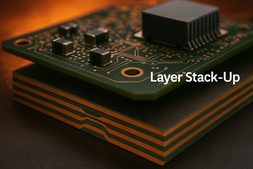
4.3 Layer Stack-Up
A well-thought-out layer stack-up can mitigate issues with thermal stress and mechanical warping. For instance, symmetrical stack-ups around the board’s center plane can prevent bowing at elevated temperatures. Place ground and power planes strategically to spread heat and maintain stable reference planes for signals.
4.4 Plan for Expansion
Account for the CTE of various materials in your design. Ensure that vias, pads, and solder joints can handle expansion and contraction across the expected temperature range. Incorporating flex or rigid-flex sections may help if mechanical stress is an issue, but be mindful of the flex material’s own heat tolerance.
4.5 Use High-Reliability Assembly Techniques
For wave or reflow soldering, ensure your temperature profiles are fine-tuned for high-temperature applications. Solder types with higher melting points (e.g., certain lead-free alloys) may be necessary to prevent re-melting in high ambient temperatures.
4.6 Reduce Mechanical Stress
Thermal cycling can cause mechanical stress between components. Add relief cuts, slots, or mechanical fasteners to help relieve stress. Additionally, consider underfill or staking compounds for large, heavy components to reinforce solder joints.
4.7 Avoid Overloading Power Traces
High operating temperatures already stress conductors. Oversizing power traces ensures lower resistance and mitigates localized heating. This approach also reduces voltage drops along the power path, improving overall system stability.
4.8 Thorough Testing Provisions
Incorporate test points and built-in diagnostics that allow real-time temperature and performance monitoring. This practice can reveal developing hotspots or imminent failures before the board experiences irreversible damage.
5. Manufacturing Processes
5.1 Fabrication Considerations
When working with specialized materials like polyimide or ceramic, the manufacturing process differs from standard FR-4. Drill speeds, lamination temperatures, and baking times must be adjusted to prevent layer separation or micro-cracking. Some materials, like PTFE, require controlled expansions during the drilling phase due to their softness and elasticity.
5.2 Soldering and Assembly
Reflow profiles must be carefully developed for each type of solder and laminate. High-temperature boards often need extended soak times or higher peak temperatures to properly wet the solder joints. The board’s density and thermal mass can significantly affect reflow uniformity. Additionally, some high-temperature boards might require special flux formulas and nitrogen reflow ovens to minimize oxidation.
5.3 Handling and Storage
Storage conditions for high-temperature PCBs are critical. Exposure to moisture can lead to delamination when boards are subjected to high reflow temperatures. Manufacturers often bake or pre-dry boards before assembly to eliminate moisture content. Proper labeling of boards, so they aren’t mistakenly handled like standard FR-4, also prevents mishaps.
5.4 Quality Control
Multiple inspections and tests are key in ensuring high-temperature boards can survive their intended environment. Automated Optical Inspection (AOI), X-ray inspection, and even micro-section analysis are standard practices. For boards destined for the harshest conditions, advanced reliability tests like Highly Accelerated Life Testing (HALT) or Highly Accelerated Stress Screening (HASS) become essential to weed out potential points of failure.
5.5 Thermal Cycling and Burn-In
Some manufacturers implement rigorous temperature cycling and burn-in procedures. Boards are exposed to repeated heating and cooling cycles or a prolonged dwell at high temperatures. These steps highlight any early-life failures or weak solder joints, allowing for design revisions or process improvements before field deployment.
6. Case Studies
6.1 Case Study: Automotive Engine Control Unit (ECU)
An automotive supplier needed an ECU capable of continuous operation at temperatures up to 150°C. PCB design engineers opted for high-Tg FR-4 material, balancing cost and performance. A six-layer board stack-up included substantial ground planes for heat spreading. To handle mechanical stress, key components were staked with epoxy adhesives. After thorough environmental testing, including extended thermal cycling and vibration tests, the ECU demonstrated excellent reliability across tens of thousands of cycles. The design overcame cost constraints by limiting the use of more expensive polyimide laminates only to the highest stress regions of the board.
6.2 Case Study: Downhole Drilling Instrumentation
A company providing measurement-while-drilling (MWD) systems required boards to survive temperatures above 175°C deep underground. Engineers selected polyimide laminates, known for high Tg and chemical resistance. Additionally, they incorporated metal-core technology for improved heat dissipation. Specialized high-temperature solder paste was used to prevent re-melting in extreme conditions. After a strict series of HALT procedures—subjecting the boards to random vibration, temperature extremes, and rapid thermal transitions—the final product maintained stable data acquisition in geological strata exceeding 180°C.
6.3 Case Study: Satellite Transmitter in Low Earth Orbit
While orbit doesn’t consistently present high ambient temperatures, the satellite faced direct solar exposure in the vacuum of space, pushing surface temperatures beyond 150°C. The chosen approach combined ceramic substrates for critical RF components and a partially rigid-flex design to accommodate mechanical movement and temperature fluctuations. Specialized coatings protected surfaces from atomic oxygen, and a series of ground-based thermal vacuum (TVAC) tests validated the design. This robust electronic design approach allowed consistent, high-fidelity data transmission from orbit with minimal performance drift over time.
6.4 Case Study: Industrial Furnace Controller
In an industrial furnace application where electronics needed to be mounted near the heat source, a multi-layer polyimide board was used. Engineers implemented extensive thermal vias under power regulators to draw heat into the system’s metal chassis. A silicone-based conformal coating protected the board from occasional chemical fumes. Real-world operation confirmed that the furnace controllers could run for extended periods at 160°C without failure.
7. Conclusion
Designing PCBs for high-temperature environments entails addressing thermal loads, material constraints, mechanical stresses, and long-term reliability concerns. By choosing suitable materials—like polyimide, metal-core, or even ceramic substrates—engineers can mitigate the challenges posed by extreme heat. But the choice of material alone is not enough; careful board layout, thoughtful thermal management, and specialized manufacturing techniques are equally crucial.
Comprehensive reliability testing, including thermal cycling and burn-in, ensures that boards remain robust throughout their operational lifecycles. As industries demand increasingly compact, high-performance electronics placed in ever more hostile conditions, PCB design for high-temperature settings continues to evolve, integrating new materials, advanced manufacturing processes, and innovative electronic design strategies.
Whether in an automotive engine bay, aerospace avionics platform, oil drilling rig, or industrial furnace, high-temperature PCBs stand at the forefront of technological development—engineered to thrive where lesser boards would fail. The synergy of carefully selected materials, precise thermal management, and rigorous testing paves the way for successful, long-lasting electronic solutions in some of the planet’s most demanding environments.