
Printed Circuit Boards (PCBs) are fundamental elements in contemporary electronics that serve as the board that brings together all the different parts of a device, whether a simple gadget or sophisticated machinery. Just like any complicated system, however, PCBs may experience issues, and one of the most frequent problems is open circuits. In this article, we will discuss what open circuits are, how they can happen in PCB design, and what you can do to detect and correct them.
Understanding Open Circuits
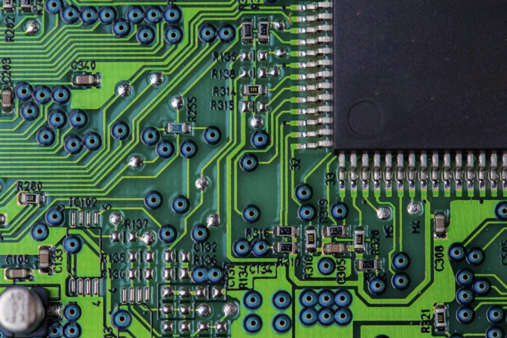
An open circuit is a break in the electrical pathway that prevents current from flowing. In the context of PCBs, this means that one or more connections between components are interrupted. This can lead to malfunctioning devices, as signals and power cannot reach their intended destinations. Open circuits can be caused by a variety of factors, including design errors, manufacturing defects, or physical damage.
The Importance of PCB Design
Before diving into the common causes of open circuits, it’s crucial to understand the significance of PCB design. A well-thought-out PCB design not only facilitates the proper functioning of a device but also minimizes the chances of failures, including open circuits. Here are some essential aspects of PCB design that can help prevent open circuits:
- Component Placement: Proper placement of components is vital. Components should be positioned to minimize the length of traces and avoid unnecessary bends that can lead to stress and breakage.
- Trace Width and Spacing: The width of PCB traces affects their current-carrying capacity. If traces are too narrow, they can heat up and eventually break, leading to an open circuit. Additionally, adequate spacing between traces is essential to prevent short circuits.
- Layer Stack-Up: Multi-layer PCBs can provide better routing options, but they also introduce complexities. A poor layer stack-up can lead to unintentional open circuits if vias (vertical connections between layers) are not properly designed.
- Design Rule Checks (DRC): Most PCB design software includes DRC tools that help identify potential issues in the design. Running these checks can catch open circuit risks before the board goes into production.
- Simulation: Simulating the circuit can help identify potential points of failure, including open circuits. This step is often overlooked but can save considerable time and resources.
Common Causes of Open Circuits in PCBs
Open circuits can arise from various factors, and understanding these causes is the first step in prevention and troubleshooting. Here are some common reasons why open circuits may occur in PCB designs:
1. Design Errors
Even the most experienced engineers can make mistakes during the PCB design phase. Common errors include:
- Incorrect Net Connections: Sometimes, nets (the electrical connections between components) may not be correctly defined, leading to unconnected paths.
- Ignoring DRC Violations: Failing to address design rule violations can result in weak connections that might break during manufacturing or assembly.
2. Manufacturing Defects
Defects during the manufacturing process can lead to open circuits, including:
- Etching Issues: During the PCB fabrication process, traces are etched onto the board. If the etching process is not done correctly, it can result in incomplete traces.
- Via Failures: Vias are crucial for connecting different layers of a PCB. If a via is not properly plated, it can create an open circuit.
3. Physical Damage
PCBs can be damaged during handling, assembly, or operation. Common causes of physical damage include:
- Mechanical Stress: Bending, twisting, or applying excessive force can break traces or connections.
- Thermal Stress: Rapid temperature changes can cause materials to expand and contract, leading to the cracking of solder joints or traces.
4. Soldering Issues
Improper soldering techniques can lead to open circuits. Common soldering problems include:
- Cold Solder Joints: A cold joint occurs when the solder does not melt properly, resulting in a weak connection.
- Insufficient Solder: Not using enough solder can prevent a good connection from forming.
How to Identify Open Circuits
Identifying open circuits in a PCB can be challenging, but several methods can help pinpoint the issue:
1. Visual Inspection
The first step in troubleshooting is often a visual inspection. Look for:
- Broken Traces: Inspect the board for any visible breaks in traces or connections.
- Cold Joints: Examine solder joints under a magnifying glass to identify any cold or insufficient solder joints.
2. Continuity Testing
Using a multimeter is an effective way to check for open circuits:
- Set to Continuity Mode: With the multimeter set to continuity mode, probe the connections to ensure that there is a continuous path.
- Test Each Segment: Test each segment of the circuit, starting from the power source to the components.
3. Functional Testing
Sometimes, the best way to identify an open circuit is through functional testing:
- Power Up the Board: If possible, power the board and observe its function. If a component is not operational, it may indicate an open circuit.
- Signal Tracing: Use an oscilloscope or logic analyzer to trace signals throughout the PCB. An absence of expected signals can indicate an open circuit.
How to Fix Open Circuits
Once you have identified an open circuit, the next step is to fix it. Here are some strategies for addressing open circuits in PCBs:
1. Repairing Traces
If a trace is broken, you can often repair it by:
- Wire Jumpers: Use a thin wire to bridge the broken trace. Solder it to both ends of the break to restore the connection.
- Conductive Paint: In some cases, conductive paint can be used to repair small breaks, though this is typically less reliable than jumper wires.
2. Reworking Solder Joints
If the issue lies with solder joints, consider:
- Reflowing the Solder: Heat the joint with a soldering iron to reflow the solder, ensuring a good connection.
- Adding More Solder: If there is insufficient solder, add more to create a solid connection.
3. Replacing Components
In cases where a component is faulty or damaged, replacement may be necessary:
- Desolder the Component: Carefully remove the damaged component using a soldering iron.
- Install a New Component: Solder in a new component, ensuring that all connections are secure.
4. Redesigning the PCB
If open circuits are a recurring issue due to design flaws, it may be necessary to revisit the PCB design:
- Reevaluate the Layout: Analyze the existing layout and make necessary adjustments to improve component placement and trace routing.
- Utilize Simulation Tools: Before finalizing the new design, use simulation tools to identify potential issues.
Conclusion
Open circuits in PCBs can be a frustrating challenge, but understanding their causes and solutions can help alleviate the problem. By prioritizing good PCB design practices, conducting thorough inspections, and employing effective troubleshooting methods, you can minimize the occurrence of open circuits and ensure your devices function as intended. As technology continues to evolve, the importance of robust PCB design and maintenance will only grow, making it essential for engineers and manufacturers alike to stay informed and proactive in their approaches. Whether you are a seasoned professional or a newcomer to the field, mastering these principles will pave the way for successful electronic design and production.