Signal conditioning techniques are essential in modern electronics, bridging the gap between raw sensor data and precise digital interpretation. In any well-structured pcb design, the quality of signal conditioning determines how accurately a system measures, processes, and responds to real-world variables. From temperature sensors and accelerometers to biomedical instruments and industrial controllers, properly conditioned signals are the backbone of reliable embedded systems. This article provides an in-depth look at what signal conditioning is, how it works, the main circuit techniques involved, and how engineers apply them to achieve stable and noise-free measurements.
What is Signal Conditioning?
Signal conditioning refers to the process of manipulating an analog signal to make it suitable for further processing by a microcontroller, ADC (analog-to-digital converter), or other digital systems. Most sensors output weak, noisy, or nonlinear signals that must be adjusted before meaningful data can be extracted. These manipulations may include amplification, attenuation, filtering, isolation, or linearization.
The main objective is to optimize the signal-to-noise ratio (SNR) and maintain the integrity of the information as it moves through the analog front end. A well-designed conditioning stage compensates for environmental noise, sensor drift, and voltage mismatches while protecting downstream components from overvoltage or transient surges.
Amplification and Attenuation Basics
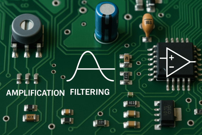
Amplification increases the strength of a small analog signal so it can be accurately processed by subsequent circuits. Operational amplifiers (op-amps) are the most common building blocks used for this purpose. For example, a thermocouple may produce only a few millivolts per degree Celsius, requiring an instrumentation amplifier to boost it to a voltage range readable by an ADC.
On the other hand, attenuation scales down large voltage signals that might exceed the input range of downstream devices. This is achieved through resistor dividers or active attenuators. Engineers often combine both techniques in a single system to normalize input levels from multiple sensors.
Precision amplification requires attention to offset voltage, common-mode rejection ratio (CMRR), and thermal stability. In high-accuracy applications such as medical or aerospace systems, low-drift and low-noise amplifiers are critical.
Filtering: Low-Pass, High-Pass, and Band-Pass
Filtering is one of the most vital signal conditioning techniques, used to remove unwanted noise and interference. A low-pass filter allows signals below a certain frequency to pass while rejecting higher frequencies, commonly applied in temperature sensors or DC measurement circuits.
A high-pass filter removes DC components and allows rapid changes in signals, useful for vibration analysis or audio processing.
Band-pass filters combine both characteristics to isolate specific frequency ranges, such as the heartbeat frequency range in ECG systems. Filters can be designed using passive components (resistors, capacitors, inductors) or active circuits involving op-amps.
In digital systems, filters may also be implemented through software-based digital signal processing (DSP) algorithms. However, analog filtering before digitization is often preferred to prevent aliasing and maintain cleaner inputs to the ADC.
Isolation Using Transformers and Optocouplers
Electrical isolation is another key concept in signal conditioning. It separates different parts of a circuit to prevent unwanted current flow while allowing data transfer. Isolation protects sensitive electronics from ground loops, high-voltage spikes, and noise coupling.
Transformers are used in AC systems to provide galvanic isolation while transferring energy or signals via magnetic coupling.
Optocouplers (optoisolators) achieve isolation through light transmission between an LED and a photodiode or phototransistor. This approach is widely used in digital communication interfaces between microcontrollers and high-voltage circuits.
In precision applications, isolation amplifiers are used to transmit analog signals across isolated barriers while maintaining signal integrity.
Common-Mode vs Differential Signals
A differential signal transmits data using two complementary lines, where the information is represented by the voltage difference between them. Common-mode noise affects both lines equally, allowing it to be canceled out by a differential amplifier.
Common-mode rejection is essential in environments prone to electromagnetic interference (EMI). For example, in industrial sensors connected over long cables, differential transmission helps maintain accuracy even when external noise sources are present.
Instrumentation amplifiers, such as the classic three-op-amp topology, are designed to provide high CMRR and precise differential amplification. This makes them ideal for pressure sensors, strain gauges, and bridge circuits.
Analog-to-Digital and Digital-to-Analog Conversion
Signal conditioning often concludes with converting the analog signal to a digital format using an ADC. The performance of this conversion depends heavily on how well the signal has been prepared. High-quality conditioning minimizes quantization errors, noise, and offset drift.
ADC resolution (e.g., 12-bit, 16-bit, or 24-bit) defines how finely the signal can be digitized. However, without clean analog input, even a high-resolution ADC yields poor results.
The reverse process, performed by a DAC (digital-to-analog converter), is also influenced by conditioning circuits such as reconstruction filters, which smooth out digital steps to restore continuous waveforms.
Sensor Signal Conditioning Examples
Different sensors require different conditioning techniques:
- Temperature Sensors (RTD, Thermistor, Thermocouple): These sensors often require bridge circuits, amplification, and cold-junction compensation.
- Pressure and Strain Sensors: Typically use Wheatstone bridge configurations followed by instrumentation amplifiers for accurate voltage measurements.
- Optical Sensors: Require current-to-voltage conversion and filtering to handle ambient light variations.
- Accelerometers and Gyroscopes: Need precision filtering and calibration circuits to eliminate offset drift.
In modern embedded systems, many sensor interface ICs combine all these conditioning elements, simplifying circuit design and reducing development time.
Temperature Compensation Methods
Temperature changes can alter sensor output, amplifier gain, and reference voltage stability. Temperature compensation techniques involve adding thermistors or digital calibration routines to maintain consistent results across operating ranges.
For analog compensation, resistor networks and diode-based circuits can counteract thermal drift. Digital compensation may use lookup tables or polynomial correction algorithms stored in the microcontroller.
Dealing with Noise and Interference
Noise can originate from switching power supplies, nearby radio transmitters, or ground loops. Techniques to minimize noise include:
- Shielded Cables: Reduce electromagnetic coupling.
- Twisted Pair Wiring: Cancels differential noise.
- Ground Planes in PCB Design: Minimize impedance and reduce EMI susceptibility.
- Decoupling Capacitors: Placed near IC power pins to suppress transient spikes.
- Analog Ground Separation: Keeping digital and analog returns apart to prevent interference.
Effective pcb design practices are critical here—signal routing, trace impedance control, and isolation zones often determine the success of noise management.
Calibration and Linearization
Even with precise electronics, sensors can produce nonlinear or offset outputs. Calibration aligns sensor response to a known reference, while linearization converts curved response characteristics into straight-line equivalents.
Calibration can be achieved in hardware using adjustable potentiometers or digitally using software compensation. Many embedded systems perform auto-calibration routines during startup to maintain accuracy over time and environmental conditions.
Choosing Signal Conditioning ICs
Selecting the right integrated circuits simplifies design and improves performance. Many manufacturers offer application-specific signal conditioning ICs for sensors such as pressure, current, or temperature.
When choosing these components, engineers must evaluate:
- Input voltage range and noise floor
- Power consumption
- Temperature coefficient
- Offset voltage and drift
- Communication interface (analog, SPI, I²C, etc.)
Popular solutions include programmable gain amplifiers (PGA), precision op-amps, isolation amplifiers, and signal chain modules that integrate filters, buffers, and ADC drivers in one chip.
Power Supply Considerations
A stable and clean power supply is vital to minimize measurement noise. Linear regulators are often preferred for low-noise analog circuits, while switching regulators can power digital sections efficiently. Proper decoupling and layout practices—such as star grounding and short return paths—help maintain signal purity.

EMI Considerations in Signal Conditioning
Electromagnetic interference can distort analog signals or cause ADC instability. Engineers apply design strategies such as RC snubbers, ferrite beads, and shielded enclosures to prevent EMI coupling. Grounded copper planes and controlled impedance routing are equally important in mixed-signal systems.
Practical Example: Conditioning for a Strain Gauge
A strain gauge is a good example of how signal conditioning integrates multiple techniques. The sensor outputs a small differential voltage proportional to strain. An instrumentation amplifier boosts the signal, a low-pass filter removes mechanical noise, and an ADC converts it for digital processing. Temperature compensation and calibration routines refine the output accuracy. This setup illustrates how conditioning forms the backbone of reliable sensor systems.
Testing and Validation of Signal Conditioning Circuits
Before deployment, all conditioning circuits must undergo testing for offset error, gain accuracy, and linearity. Tools such as oscilloscopes, spectrum analyzers, and function generators verify that the signal maintains fidelity across operating ranges.
Automated testing systems can record data over temperature and load variations to confirm stability and repeatability.
Integration into Embedded Systems
Signal conditioning does not operate in isolation—it is tightly coupled with microcontroller firmware, ADC drivers, and communication protocols. Many modern embedded boards integrate analog front-end ICs directly into their designs, improving precision while reducing footprint. Efficient PCB layout and grounding techniques are central to these systems.
Future Trends in Signal Conditioning
Emerging trends include digital calibration ICs, programmable analog front ends, and software-defined signal processing. AI-based algorithms are also being introduced to detect noise patterns and automatically tune filters for changing conditions.
Miniaturization and low-power design are driving innovation, especially in IoT and wearable applications where every milliwatt and millimeter count.
Conclusion
Signal conditioning techniques form the foundation of accurate, stable, and reliable measurement systems. From simple filters and amplifiers to advanced isolation and calibration circuits, each step in the chain contributes to high-quality data acquisition. Engineers must consider component characteristics, temperature effects, noise sources, and grounding strategies when designing these systems. Integrating these principles early in pcb design ensures efficient development and superior product performance.
